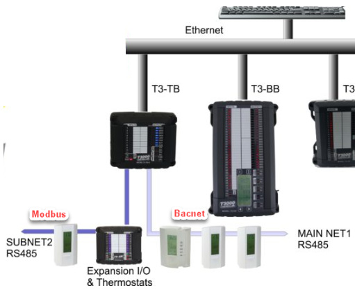
Here is an example program showing how to read bacnet and modbus devices wired to the subnetworks of the T3 controller. The two subnets are set up on the RS485 bus connections of the T3 controller, one will have the modbus devices and the other will have the bacnet devices. Note that you cannot mix modbus and bacnet devices on the same subnetwork or you’ll have communications errors.

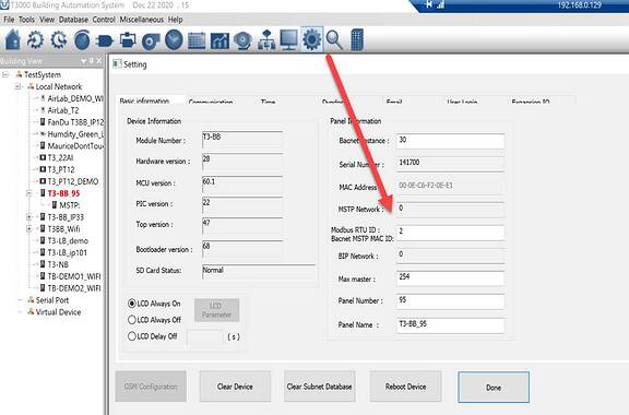
Click on the node at Tab1 and then on the gear icon at Tab2 to bring up the advanced setup screen for the T3 controller. The IP address is set as fixed with the last octet of the IP address used as the panel number at the two Tab3’s. These two items need to be the same in order for the network routing rules to work. We need to make this more intuitive and will work up something for the user interface soon.
Lower down are the protocol and baud rate settings for the two subnetworks. One of the subnets is referred to as ‘main’ and it is set to Bacnet MSTP protocol at Tab5. The other subnet is referred to as ‘sub’ and this is set to Modbus at Tab 4. There’s no difference between the main and the sub except the name, both networks support Modbus and Bacnet equally well.
It goes without saying that any devices connected to each of these networks must be set to the same protocol and baud rate or the communications will not work for one or possibly all devices on that subnet.
After T3000 builds the network connections you will see the devices in the tree at Tab 6.
[Update]: Now both bacnet and modbus devices will show up here, before it was only modbus but now device discovery for both protocols is fully supported.
Next we create some variables to hold the data from the network at Tab8, give them names and set the engineering units in the variables table. Notice at Tab9 that the values are zero becuase there is no program associated with these variables yet.
Next we create a short program to read and write some network points. Click on the programming icon at Tab 10 to bring up the list of programs running in this controller, each row represents one program. Click on the first row at Tab11 and hit the “Insert” key to bring up the program editor at Tab12.
Further down is a listing of the program. You can mix bacnet and modbus commands in the same program, the controller will take care of routing the traffic to the appropriate subnetwork.
Lines 40 and 50 are the bacnet commands which make use of the bacnet ‘AI’ keyword for analog input. The ‘28’ is the panel ID of the T3 controller itself followed by a ‘.’ to denote the subnetwork and then the address ID of the subnet device, ‘12’ in this case.
40 TEMP1 = 28.12.AI1
50 HUM1 = 28.12.AI2
Lines 90 and 100 are the modbus commands to read the corresponding data using modbus registers. The format is similar to the bacnet commands, using the ‘MAIN.SUBNET’ notation to refer to the T3 controller ID and the subnet node ID. Finally, note that modbus registers are integer values x 10 so we need to divide by 10 to get the actual value.
90 TEMP2 = 28.84.MB_REG101 / 10
100 HUM2 = 28.84.MB_REG304 / 10
*******Here is the whole program for reference **************
10 REM READ MSTP POINTS
20 REM — 28 → ADDRESS OF THE CONTROLLER, (LAST OCTET OF IP ADDRESS)
30 REM — 12 → SUBNET MSTP BACNET DEVICE ADDRESS
40 TEMP1 = 28.12.AI1
50 HUM1 = 28.12.AI2
60 REM READ MODBUS POINTS
70 REM — 28 → ADDRESS OF THE CONTROLLER, (LAST OCTET OF IP ADDRESS)
80 REM — 84 → SUBNET MODBUS DEVICE ADDRESS
90 TEMP2 = 28.84.MB_REG101 / 10
100 HUM2 = 28.84.MB_REG304 / 10
Here is a list of the network points activity generated by a typical control program, these network points are generated automatically and transparently for you any time you use an item which is not located on the local controller. In this example we see two modbus register reads to two separate thermostats using modbus register reads. You can see the devices are online and reporting some data under the value column.
TBD: Explain the “Time Remaining” column.


