A question came in today on how to set up a potentiometer for use as a setpoint adjustment knob. We had a 10k pot on hand and wired it directly to one of the inputs of the T3 controller.
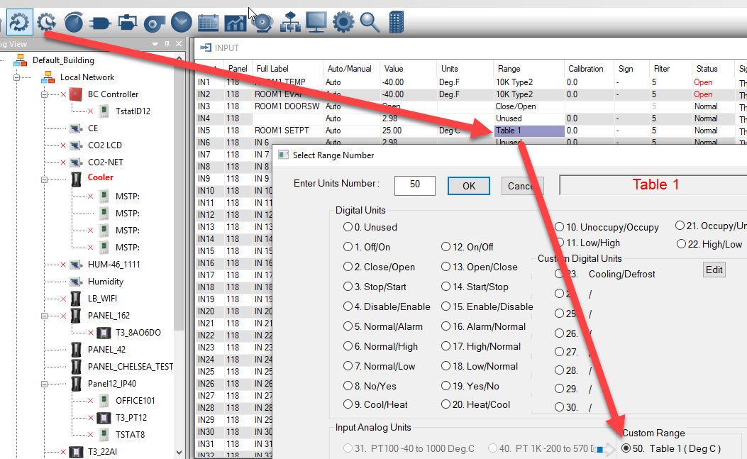
First configure the input to use custom analog range ‘50’ as shown.
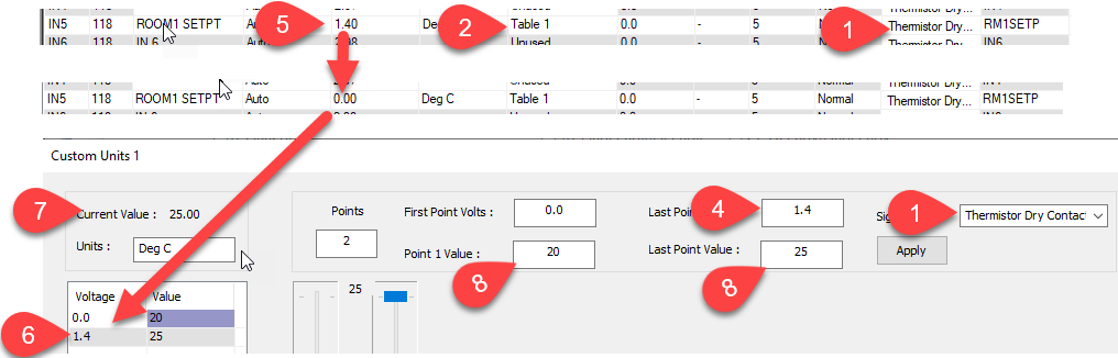
This brings up the custom range dialog where you can fill in the range for the potentiometer. The T3 controller uses an excitation voltage of 3V which is connected through a 10k pullup resistor for reading thermistors and dry contacts. This means we should see the voltage on the input swing from 0V to 1.5V when the pot goes through its full range of motion from 0 ohms to 10k ohms. We fill in these expected voltages at Tab4 and the corresponding min/max setpoints we want at Tab8. We’re using a linear pot so we only need two data points in our custom table. Be sure to select thermistor/dry contact as the signal type at Tab1.
I had to tweak the max voltage value at Tab6, lowering it from the expected 1.5V down to 1.4V. As I did this I moved the pot to min and max position a few times till I got the value at Tab7 to properly reflect the desired min and max setpoints at tab8.
Final Notes: 10k ohm pots will give you the best response for a given rotation of the potentiomenter but you can use pots of other values, just adjust the voltage value at Tab6 accordingly. The downside to using larger or smaller pots is that the pot will be less sensitive to motion.
1 Like
Supplementary question…
I would like to use a potentiometer or similar to simulate a 0-10V signal input (eg from a pressure sensor) for testing. I dont understand how a 0-10V input interacts with the 3V excitation - please explain?
I tried connecting a pot as a simple voltage divider from 24Vdc T3 supply rail to GND. Input configured as 0-10V (%) - but the result was always 99.8% ie top-of-range - probably overflowed. Result did not change with pot rotation
I am now thinking about a variable voltage regulator (eg LM317).
Any other ideas or limitations to be aware of?
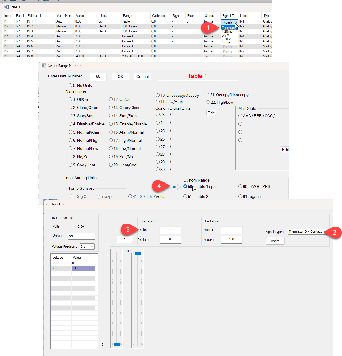
You could consider tying the 10k pot directly into the inut and use the on board weak excitation voltage, select a custom analog signal at Tab4. In this range you would set the input signal to dry contact/thermistor as shown at Tab2. You could then scale the range using a custom analog input and filling in the pressures and voltages to suit your application at Tab3. You could calculate these numbers out knowing the pullup voltage is 3V and your pot resistance is 10k for example, but it would be faster to just crank the pot counterclockwise and take the low scale reading, then crank the pot the other way to get the high scale reading.
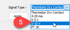
You could use a 24VDC external excitation voltage as you mentioned, you would need to set the range to 0-10V at Tab5 to disable the on board 3V excitation voltage.
When you are done the experiment and ready to connect the real pressure sensor you would build a new custom table to match your pressure sensor and make sure to set the signal type to 0-10V.