For example, we have one AI and need to monitor 3 dry contacts. Now i wire them in series and have open contact if any or contacts is open, and need to check which of them is open on site. If i put them in parallel with different resistors may be i can detect which one is open remotely.
I found some useful info in other topic about potentiometer which gave me idea of how it can be done, but still if there is good practice how this could be implemented i would be glad to know it.
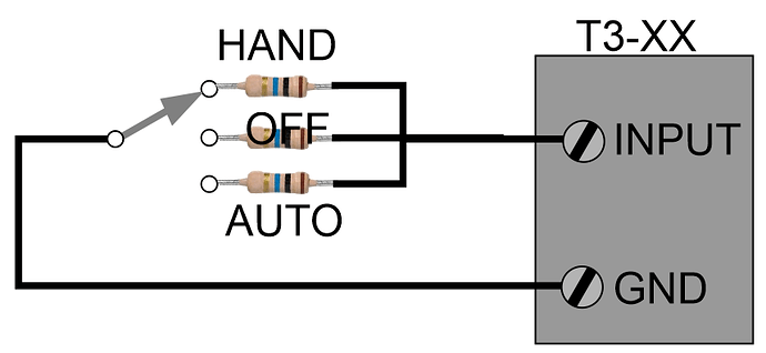
If I understand correctly you want to detect three dry contacts with one single input. You could do it with three resistors wired like so or in parallel as you suggest.
Set the range to a custom range like the potentiometer example above then write a program to detect the current reading and convert that into three discreet states.
10 IF SWITCH1 <= 100 THEN VAR1 = 1
20 IF SWITCH1 >= 101 AND SWITCH1 < 200 THEN VAR1 = 2
30 IF SWITCH1 >= 201 THEN VAR1 = 3
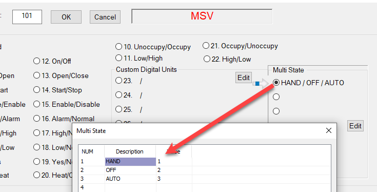
Use the new multi-state variables to store the state of the three position switch in VAR1. You can insert this variable on the graphics displays and see the state of the hand-off-auto switch there as well.
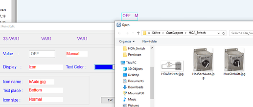
For bonus points: Create a different icon for each state, we’ll need to work on the T3000 interface a bit to enable this but its on the todo list.
Is the new MSV a bacnet object? That would be awesome if it was.
For now its an AV, we’ll make it into an MSV next step.
My task is a bit different. Question is, if I would be able to reliably detect 0,5kOhms resistance change in range of 2,1kOhm-10kOhm.
Below scheme and table of possible combinations. I made excel table and played a bit with different resistors values, best option i found is 10kohm 6kohm 5kohm combination.
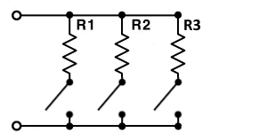
| R1 | R2 | R3 | ||
|---|---|---|---|---|
| 10 | 6 | 5 | kOhm | |
| Y | Y | Y | 2,1 | |
| N | Y | Y | 2,7 | 0,6 |
| Y | N | Y | 3,3 | 0,6 |
| Y | Y | N | 3,8 | 0,5 |
| N | N | Y | 5 | 1,2 |
| N | Y | N | 6 | 1 |
| Y | N | N | 10 | 4 |
resist swich calculator.xlsx (9.7 KB)
At the risk of stating the obvious, wouldn’t it be simpler and more robust to simply replace your existing T3 with a T3-BB? That has a ton of inputs and would make troubleshooting a lot easier.
Ignore this response if this is a hobby thing and/or $$'s are an issue.
It is mechanical fire dampers with normally closed switch if damper is opened. That damper can close only in case of fire if temperature in vent system will rise, this is not something happens often. By design 3 switches are in one group connected in series an only groups are monitored. So in fact, this is part I am having fun in this project, and try to do something new, because other than that all this installation is boring.
This will definitely work, its a good application so I have asked my crew to wire up an example and I’ll post again soon.
@tdawgtoo: This can be useful if you’ve got a lot of switches to wire up like monitoring a bank of contactors in an MCC. Could also be useful if you only have two conductors like Andrius’ retrofit situation.
Updated: Well this task got me hooked and I spent a lot more time than I imagined on it. Once into it I realized it is a lot like the ‘Resistor Divider Network’ board I did ages ago. We used to run into chillers with a potentiometer to adjust the setpoint. In order to control them we used an analog output that tied into a small transducer type circuit board with 8 relays on it, each of the relays contributed a binary addition to the total resistance. Its called an R2R resistor ladder and is hooked up like so in this example. I added a resistor R4 to the end of the network to detect an open circuit condition.
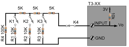
Then I simulated the whole thing in an electronics package called Multisim from labview.
And I built a spreadsheet to graph it all out, probably could have done this in Multisim but this was quick.
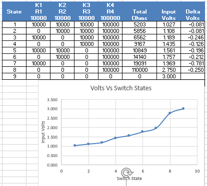
One task left to do now is to test it all out on the T3 controller, I may even have the crew here add some new special ranges for one, two and three switches to make things even easier.
Coworker suggested to wire switches in series with parallel resistors. ![]()
Question is how controller will react to short and do i need resistor on line. In normal state all switches will be ON so line will be shorted if i will not put any resistance on line.
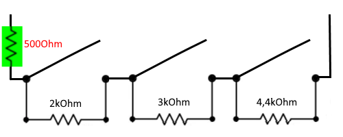
Correct, if any switch shorts then you would not be able to detect the other sates. See above for the ideal solution. Will write a program for it when I have a moment.
