I have a T3-TB that I installed about a week and a half ago (12th of May), 2 of the inputs are 4-20mA, another is a 10k T2 sensor, and the rest of the inputs are Hi/Low, On/Off, Off/On etc.
I had configured the inputs as described, and was getting the right values out of it via a modbus poll from another device. However the next day when I went to do some work on the other device’s code remotely (It was a Saturday), the inputs were showing a value around 3000. They should have been around 6.5mA or 6500. I went to site the following Tuesday, and noticed when I brought up the controller in the T3000 tool, all inputs were set to “unused”. I programed them back up, and left site. I have checked again this afternoon, and they are once again all back to “unused”.
Am I doing something wrong here?
Haunt seen that sort of behavior before. One small thing to point out is you can save your work, all the configuring of inputs, you can save that in a prog file so that if it does happen again you can just reload the prog file. Navigate to T3000 → file → save-as for saving and ‘load’ for sending it back to the controller.
One thing which can trip up the controller is ground loops, especially with something like 4-20ma transducers. Be extra careful that the supply for that transducer is isolated from the supply of the T3 controller. Tie the GND of that supply to the GND of the T3 controller. Tie the GNDs of everything to earth at each cabinet.
You could send on the details of the 20ma sensor and power you’re using for it and maybe I can spot something.
I can confirm all grounds are common, (single cabinet on site, and remote 4-20 devices are cabled back to this cabinet).
The 4-20mA devices are Hyquest shaft encoders.
Due to the remote nature of the site, and limited hardware on site, I am only able to connect via the T3000 software using my laptop. So I have gone for the approach of writing the input type’s via modbus. And I have set that up on my main controller’s code, and easily dump it into the T3-TB remotely if required.
I see one thing which may be at play here, the sensor will shut down to save on battery power. I dont know how it decides to wake up… but the T3 is doing its own thing as well on the 4-20ma range, it is muxing the signals very quickly. Each input only sees the 4-20ma circuitry for a few millisconds per scan. Your device mentions it needs 200ms before it powers up the 20ma output and stabilize which is longer than our mux sits on one channel. We solved this issue for our own hum sensors by adjusting the timing on both our sensor device and our T3 device. If we had one of your sensors to experiment with we could make sure they are compatible.
For now the only workaround I can suggest for now is to drop the 4-20ma signal through a 250 ohm resistor to convert it to a 0-10V signal and work with that. The T3 input would then of course need to be set to the 0-10V signal type and do a custom input range for the 2V and 10V end of scale readings.
Be sure to save the prog file, when this happens the settings are sent to flash. ALso when you reload the prog file the settings will be saved to flash. I dont know how come you lost your settings but it could be something to do with sending them over Modbus. Our device is used to working with T3000 and it may need to be forced to flash the settings when using Modbus writes. I will check with the team on this.

The reason why you changed the range , but it shows unused , is that the range value you wrote through the third-party modbus software is a wrong range.
For range details, see the following
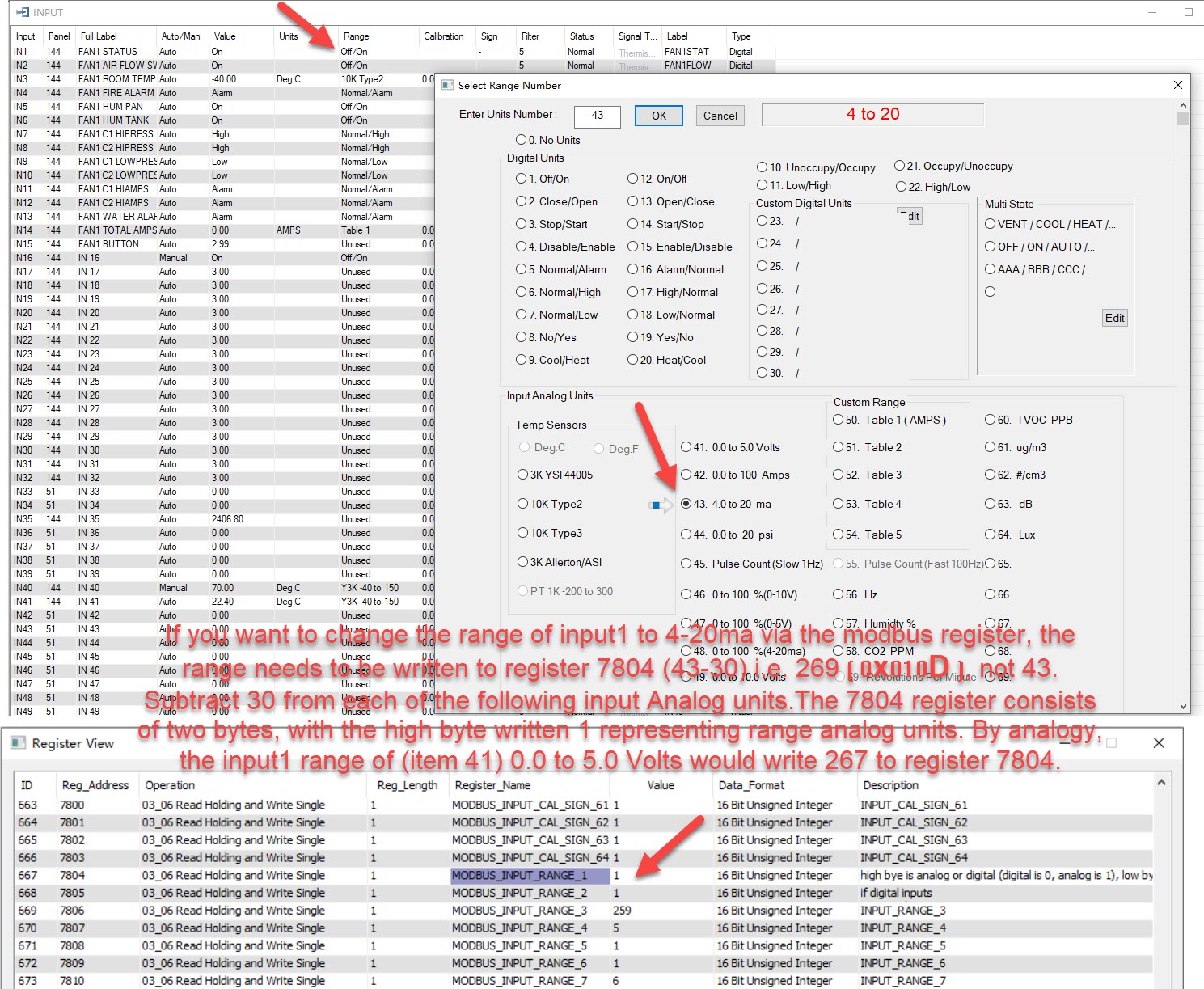
If you want to change the range of input1 to 4-20ma via the modbus register, the range needs to be written to register 7804 (43 subtract 30 = 13) , use 13 as low byte . And use 1 as high byte ,combine value is 269 ( 0x010D ).
Subtract 30 from each of the following input Analog units.The 7804 register consists of two bytes, with the high byte written 1 representing range analog units. By analogy, the input1 range of (item 41) 0.0 to 5.0 Volts would write 267 to register 7804.
if you want change input1 to digital units like (2. Close /open) 7804 register high byte should be 0 , and low byte should be 2 ,so write (0x0002 ) to 7804 will change to Close /Open
Sorry for the trouble with our setup, the main reason is the firmware engineer to save flash.
Sorry Fan_Du for the confusion, but The first two times I changed the range was through the T3000 software.
And only after that, as a failsafe/ workaround did I write to the modbus addresses 7804.
I have a control stratagy in place on my main controller. Which does the following: Reads the 7804 register and checks if the value is 269, and then if it isnt a 269, I am then writing 269 to 7804.
(and the same for the other inputs with their respective values)
Hope that clears things up.
As I replied above, I only sent the values over modbus, as it had revereted to unused after I set them using the T3000 software twice before (and the site is in a difficult area to get to, with several river river crossings so only a 4x4 can access it, so I would do anything to not have to try and get to the controller physically!)
The graphic you have shown, is for a seperate battery powered data logger that you can use to take measurements in offgrid remote locations. And it is totally seperate of the encoder. The current draw from the encoder itself is constant.
When I set these devices up origionally, I had them set to 0-10v with a resistor accross them (As I was aware of the issue with the input being muxed). I changed them to 4-20ma on my next site visit as I had some more time to test to see if it would work on 4-20 nativley, and the measurements were rock solid.
|
Bubblegoose
May 23
|
- | - |
As I replied above, I only sent the values over modbus, as it had revereted to unused after I set them using the T3000 software twice before (and the site is in a difficult area to get to, with several river river crossings so only a 4x4 can access it, so I would do anything to not have to try and get to the controller physically!)
<Things are tough there on your site, yikes.
The graphic you have shown, is for a seperate battery powered data logger that you can use to take measurements in offgrid remote locations. And it is totally seperate of the encoder. The current draw from the encoder itself is constant.
That screen shot came from your datasheet that you linked before for your sensor. Please send on some info about your sensor specifically and that will save us all some time.
When I set these devices up origionally, I had them set to 0-10v with a resistor accross them (As I was aware of the issue with the input being muxed).
Glad to see folks are getting some use from this forum. Thanks for that.
I changed them to 4-20ma on my next site visit as I had some more time to test to see if it would work on 4-20 nativley, and the measurements were rock solid.
Keep in mind there is both a range setting At tab2 and a ‘signal type’ setting at Tab1.
So you may need to be writing to two modbus registers as well as several other parameters if custom engineering units table at Tab3 is not being written and saved properly. Its best to save all this into a prog file and reload if you do lose settings.
And once we get to the bottom of this you should never have to resort to sending data to modbus registers to a device that somehow loses its settings, we need to focus on that for now I would say. Perhaps you’re somehow writing some data which resets & clears the controller, you could set up a test in the office to try & repeat that. Any routines which write data rather than read data, set that up times 10, put the T3 through the worst case scenario with lots of random reads & writes from your application.

Saving the range settings through T3000 should for sure save them to flash, there might be a slight delay to avoid writing to flash too often is all.
Glad you found a workaround but normally that should not be required at all. T3 controllers save their configs as set up from the T3000 software as you work. They do not loose any settings after random resets. If you are experiencing that then we’ll need to dig deeper on this project.
Yes it’s easy to get off track. I do have the controller logging to an external database. So if it does get a wrong register value returned, not only will it write the correct value again, but it will log it so I can monitor it over time. And hopefully see if there are any corrolations to other data.
I will setup a test T3-TB unit in the office tomorrow on a test bench and get a bit of a torture test started.