PID control and staging outputs

I’m really liking this controller platform. I have built custom ranges for some pressure transducers, and want to trigger outputs based on the PID loop output.

Let’s say I am attempting to maintain a suction pressure setpoint of 45psig.

I have 4 available outputs, with different capacities, that can be used to maintain the setpoint depending on what the pressure does, and how fast. (Eg, PID) If the pressure goes up, more pumps come on. pressure goes down, pumps turn off.

Say I have 4 pumps, with available capacity of 10% 20%, 30%, 40%. Meaning if everything was feeding to the suction header wide open, you would need pumps 1,2,3,4. If you were only running at a little below 50%, you may only need pump 4. If running at 25% capacity, it would only run pump 2, and occasionally bring on pump 1.

I’d have a 2psig deadband, so as the suction pressure creeps up or down, it would need to stage pumps on of off to stay within that deadband.

Ideas? Questions?

1 Like

I cant see why you are interested in the Pump Suction pressure.
Is it a closed water pumping system? Like Chiller and Fan coils?
In most HVAC Systems, We dont care about pressure, we care about volume of fluid.
We calculate this by using a Differential pressure transducer across the supply and suction lines. In a modern system with 2 way control valves, you would also need a bypass valve at the end of the line to generate minimum flow conditions if all of the valves shut.
It is very difficult to maintain either suction or discharge pressure on a pumping system with the average HVAC equipment available.
I havent looked at the PID loops here yet.
However most produce a linear number with a range of 0-100. Most people use this as a percentage. But ive also seen 0 to1, -1 to1 (generally used for tristate devices), 0 to10, 2 to 10 and -1 to 10,000. Some have resolutions in the 4 to 6 decimal point range. But for the most part they are all converted to 0-100%

What exactly are you trying to control?

About the multiple pumps. Bad Idea. Always use a single pump with an inverter and if necessary a second pump as a backup. Multiple pumps fight each other and lead to unexpected results that generally you wont like.

“In most HVAC systems…”

Please remember, some people do not work on the same things you do. I tried to be generically descriptive to avoid giving too many people the same idea.

I work on heavy commercial and industrial refrigeration.

There will be several “circuits” tied to a common header. (Say 6 different walk in coolers).

Each cooler temp is controlled via a Inlet Pressure Control that maintains evaporator pressure to maintain temp on a “24/7” on time except for defrost.

This is done for product integrity and efficiency.

All these circuits pipes to a common header, and the pressure fluctuates depending on defrost and load on the individual coolers.

So, if 4 are kept closed for 24 hours and at temp, the load is low, then 1 goes into defrost, so no load. Then one is being stocked, so has a high load. Then defrost stops, and load increases. Then everything is closed overnight, and load really drops. The next morning, truck comes in and all coolers are opened and load is at max.

This is what I am trying to control.

Refrigeration. Not on/off air conditioning.

And for that matter, I never said I was working on HVAC. Why did you jump to conclusions?

1 Like

Because you used the term “PUMP” instead of “Compressor”
By the way. Im a Mechanical Engineer and have specialized in Refrigeration and controls since 1980.
Good luck with your project. Just keep plenty of connecting rods and pistons handy for the rebuilds.
You are going to need them.

There are hundreds of thousands of systems out there running right now exactly like I described. If you were truly a mechanical engineer that has specialized in refrigeration, you would have known exactly what kind of system I am talking about.

As a matter of fact, I can name 3 “Big Brand” control systems that do exactly what I am trying to do, without having to keep pistons and connecting rods handy. But just the “controller” cost as much as one of those compressors. And it has no input or outputs. You still have to buy more hardware.

You should open your mind a little. At this point, I love the controller, but the forums are garbage if this is the attitude I am going to get. I thought this was about working to create something better, but apparently you have it all figured out.

And for what its worth, I could have said “valve” or “relay” or “light level” or any other term.

A compressor IS A pump.

Now, anyone else actually want to help or have I stumbled upon another group of closed minded people that don’t want to improve what’s offered in the market place?

I asked for help, not criticism, and on my first post to this forum, you spent 85% of your response criticizing what I am trying to do without asking questions.

THEN you asked the pertinent question, and criticized my response!

So, what good did you do? Nothing.

Now,

Let’s see what kind of response i get with this reworded…

Let’s say I am attempting to maintain a suction header pressure setpoint of 45psig on R407a, who’s SST at 45psig is 22deg F (meaning a coil temp of 22deg F), this is the lowest walk in cooler evaporator setpoint of 22deg F SST, which will give the lowest temp cooler a operating temp of 32deg F. Pretend there are 6 systems feeding back to this header. The EPR is set fully open for cooler 1, which has a setpoint of 32 deg F. Coolers 2 and 3 EPR’s are set to 25deg F SST, for a 35deg F cooler, and cooler 4 is set to 35deg F SST as a prep/cutting room of 45 deg F. Coolers 5 and 6 have an SST of 32deg F for a cooler temp of 42deg F (produce storage).

Pretend total refrigeration load for this system is 75,000btu.

I have 4 available compressors, with different capacities, that can be used to maintain the setpoint depending on what the pressure does, and how fast. (Eg, PID) If the pressure goes up, more pumps come on. pressure goes down, pumps turn off.

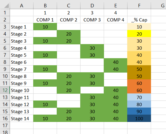
The compressors have the available capacity of 10%(7,500BTU), 20%(15,000BTU), 30%(22,500BTU), 40% (30,000BTU), for a total of 100% load of 75,000BTU. Meaning if everything was feeding to the suction header wide open, you would need pumps 1,2,3,4. If you were only running at a little below 50% (say 35,000BTU), you may only need pump 4. If running at 25% capacity (18,500BTU), it would only run pump 2, and occasionally bring on pump 1. If running at 60% (45,000BTU), it would only need compressor 4, and ocassionally1. The suction header pressure will fluctuate depending on load and defrost schedule.

I’d have a 2-4psig deadband (depending on how the T3000 interprets deadband. Some controllers add the “deadband setting” to each side of the setpoint, and some split the difference), so as the suction pressure creeps up or down, it would need to stage pumps on of off to stay within that deadband without bringing on too much capacity and short cycling (which I am sure the person responding to this question is worried about)

How do I turn the PID loop output into deciding what compressor(s) to start or stop based on whats already running and choosing from what’s available to start, or what’s running to stop?

If the PID calculation is raising slowly, then it would bring on a smaller compressor. If the pressure rose quickly (2 coolers were off for cleaning overnight and restarted the next morning), it would bring on a bigger compressor due to the speed of climb.

Soooo, again… Ideas? Questions?

I’ll figure it out, but I was hoping someone else already did.

Here are the different combinations of “stages” I’m trying to figure how how to choose from.

Say we are at Stage 8, and the pressure increases slowly, the control would go to stage 10. But if it increased quickly, instead of banging through the stages, it would calculate to jump to say, Stage 12. It would wait a predetermined amount of time (say 60 seconds), and check the PID against what was needed, to stage up or down, and choose depending on the speed of increase or decrease.

Will a PID output percentage go negative? I think that may be the key to the whole thing. If PID output is low, the calculation will not do anything. It works as the output goes higher. The output would have to be a negative percentage to figure a stage down, would it not?

I could be overthinking the whole thing, but that’s why I am here.

Also, To help equalize runtime, it would be nice to use even stages going up in capacity on Stages 5-10, and odd when decreasing capacity. But that’s a whole other discussion most likely.

Screenshot (3)

2 Likes

I found this that might work, but I cannot find the advanced PID settings…

This is for a tstat8 with its canned logic and PID table set up.

If you are working with the programmable T3 series or the tstat10 then you can hit the F1 function key to bring up the help system where you can search for keyword PID for more info.

Which device are you working with?

Maurice Duteau

I thought that looked like it was for one of the tstats, but wanted to make sure.

I am using the T3TB8i. I have gone through the help screens, and understand (or am learning) how the PID works, or how it calculates, but it shows heating and cooling in pretty much fixed steps. All I am doing is cooling,

For cooling the ‘action’ term gets set to plus. Opposite for heating. You can set the set point and temperatures to manual mode and force them up & down to simulate temperatures to see things in action.

Maurice Duteau

I’ve been experimenting with T3000 software for a while and can give you an idea where to start with your program.
To set PID loop for “input” put your input# where your transducer is connected to, for setpoint value assign a variable and make it “0” , “action” put “+” and Prop value put your maximum input value, 45.
That will give you PID output 0-100 with your input change 0-45.
You need to assign variables for some values in my example var32 = actual stage, var33 = differential for stages, var50 - var63 = stage switching values, var70 - var83 = stage switching values - differential.
I’m giving you example for 3 stages to fit it on the screen shot but to add each stage you need to add logic line, stage with outputs assigned and line in differential section, up to 14 stages.
Good Luck.

1 Like

Thank you so much.

I’ll play with that this evening.

Thanks for chiming in Twmicun. I will offer up a few tips that I like to follow when doing this control basic programming, the main one being to let the logic flow, avoid gotos by adding overrides and higher priority statements towards the end of the program. This makes the program easy to follow later.

Here;s a partial example but you will see the same strategy used in all the examples here, the program flows from top to bottom without gotos and avoids explicitly setting those outputs like your lines 20 through 60 each scan.
09 REM ******* COOL1, 2, 3 ARE VIRTUAL VARS **********
10 IF PID1 > 25 THEN START COOL1
20 IF PID1 > 50 THEN START COOL2
30 IF PID1 > 75 THEN START COOL3
40 IF PID1 < 20 THEN STOP COOL1
50 IF PID1 < 40 THEN STOP COOL2
60 IF PID1 < 65 THEN STOP COOL3
70 REM ***** ENABLE THE OUTPUTS ********
80 IF COOL1 OR COOL2 OR COOL3 THEN START COOLFAN
90 IF NOT COOL1 AND NOT COOL2 AND NOT COOL3 THEN STOP COOLFAN
100 IF COOLFAN THEN START COMPRSR ELSE STOP COMPRESR

1 Like

I see Maurice your idea of staging program and that would work fine for regular staging where you add another stage if PID output rises. If Christopher had 10 compressors 10% of the load each adding one of them on every 10% PID output rise would work perfect and would be simple to program. Unfortunately in his project it is a sequencer that has specific set of outputs for each stage. Regular staging program will not work here.

What about bringing on more than one output at the same time?

90 IF PID < 1 THEN STOP COOL 1 AND STOP COOL 2 AND STOP COOL 3 AND STOP COOL 4

100 IF PID1 > 1 AND < 6 THEN START COOL 1 AND STOP COOL 2 AND STOP COOL 3 AND STOP COOL 4

110 IF PID > 5 OR < 16 THEN STOP COOL 1 AND START COOL 2 AND STOP COOL 3 AND STOP COOL 4

120 IF PID > 15 AND < 26 THEN START COOL 1 AND START COOL 2 AND STOP COOL 3 AND STOP COOL 4

130 IF PID > 25 AND < 36 THEN STOP COOL 1 AND STOP COOL 2 AND START COOL 3 AND STOP COOL 4

140 IF PID > 35 AND < 46 THEN START COOL 1 AND STOP COOL 2 AND START COOL 3 AND STOP COOL 4

150 IF PID > 45 AND < 56 THEN START COOL 1 AND STOP COOL 2 AND STOP COOL 3 AND START COOL 4

160 IF PID > 55 AND < 66 THEN STOP COOL 1 AND START COOL 2 AND STOP COOL 3 AND START COOL 4

170 IF PID > 65 AND < 76 THEN STOP COOL 1 AND STOP COOL 2 AND START COOL 3 AND START COOL 4

180 IF PID > 75 AND < 86 THEN START COOL 1 AND STOP COOL 2 AND START COOL 3 AND START COOL 4

190 IF PID > 85 AND < 96THEN STOP COOL 1 AND START COOL 2 AND START COOL 3 AND START COOL 4

200 IF PID > 95 AND THEN START COOL 1 AND START COOL 2 AND START COOL 3 AND START COOL 4

I don’t know how your system works, I never came across system like that. But in your example at the edge of stage switching, PID5,15,25,35,45,55,65,75,85,95, two stages will run, new and previous so your output is more then double. Is that acceptable? Won’t it negatively effect your system operation?

| christopher.russell
September 7 |

  • | - |

What about bringing on more than one output at the same time?

90 IF PID < 1 THEN STOP COOL 1 AND STOP COOL 2 AND STOP COOL 3 AND STOP COOL 4

100 IF PID1 > 1 AND < 6 THEN START COOL 1 AND STOP COOL 2 AND STOP COOL 3 AND STOP COOL 4

110 IF PID > 5 OR < 16 THEN STOP COOL 1 AND START COOL 2 AND STOP COOL 3 AND STOP COOL 4

120 IF PID > 15 AND < 26 THEN START COOL 1 AND START COOL 2 AND STOP COOL 3 AND STOP COOL 4

130 IF PID > 25 AND < 36 THEN STOP COOL 1 AND STOP COOL 2 AND START COOL 3 AND STOP COOL 4

140 IF PID > 35 AND < 46 THEN START COOL 1 AND STOP COOL 2 AND START COOL 3 AND STOP COOL 4

150 IF PID > 45 AND < 56 THEN START COOL 1 AND STOP COOL 2 AND STOP COOL 3 AND START COOL 4

160 IF PID > 55 AND < 66 THEN STOP COOL 1 AND START COOL 2 AND STOP COOL 3 AND START COOL 4

170 IF PID > 65 AND < 76 THEN STOP COOL 1 AND STOP COOL 2 AND START COOL 3 AND START COOL 4

180 IF PID > 75 AND < 86 THEN START COOL 1 AND STOP COOL 2 AND START COOL 3 AND START COOL 4

190 IF PID > 85 AND < 96THEN STOP COOL 1 AND START COOL 2 AND START COOL 3 AND START COOL 4

200 IF PID > 95 AND THEN START COOL 1 AND START COOL 2 AND START COOL 3 AND START COOL 4

I would like to understand how your system works. Can you draw refrigerant line diagram marking major components (compressors, condenser, evaporators, expansion valves). Also mark your pressure sensor, that controller is gonna read, location. Short sequence of operation would help.

I don’t know how your system works, I never came across system like that. But in your example at the edge of stage switching, PID5,15,25,35,45,55,65,75,85,95, two stages will run, new and previous so your output is more then double. Is that acceptable? Won’t it negatively effect your system operation?

| christopher.russell
September 7 |

  • | - |

What about bringing on more than one output at the same time?

90 IF PID < 1 THEN STOP COOL 1 AND STOP COOL 2 AND STOP COOL 3 AND STOP COOL 4

100 IF PID1 > 1 AND < 6 THEN START COOL 1 AND STOP COOL 2 AND STOP COOL 3 AND STOP COOL 4

110 IF PID > 5 OR < 16 THEN STOP COOL 1 AND START COOL 2 AND STOP COOL 3 AND STOP COOL 4

120 IF PID > 15 AND < 26 THEN START COOL 1 AND START COOL 2 AND STOP COOL 3 AND STOP COOL 4

130 IF PID > 25 AND < 36 THEN STOP COOL 1 AND STOP COOL 2 AND START COOL 3 AND STOP COOL 4

140 IF PID > 35 AND < 46 THEN START COOL 1 AND STOP COOL 2 AND START COOL 3 AND STOP COOL 4

150 IF PID > 45 AND < 56 THEN START COOL 1 AND STOP COOL 2 AND STOP COOL 3 AND START COOL 4

160 IF PID > 55 AND < 66 THEN STOP COOL 1 AND START COOL 2 AND STOP COOL 3 AND START COOL 4

170 IF PID > 65 AND < 76 THEN STOP COOL 1 AND STOP COOL 2 AND START COOL 3 AND START COOL 4

180 IF PID > 75 AND < 86 THEN START COOL 1 AND STOP COOL 2 AND START COOL 3 AND START COOL 4

190 IF PID > 85 AND < 96THEN STOP COOL 1 AND START COOL 2 AND START COOL 3 AND START COOL 4

200 IF PID > 95 AND THEN START COOL 1 AND START COOL 2 AND START COOL 3 AND START COOL 4

You mentioned that the staging would not work because certain outputs need to go on in certain stages. There is an easy way to accomplish this in the programming, I can recall programming a six or seven stage boiler system with lead/lag rotation which sounds similar, the program went something like this:

1 REM ******* DECIDE HOW MANY STAGES SHOULD BE ON *******
10 IF PID1 < 15 THEN NUMSTAGE = 0
20 IF PID1 > 20 THEN NUMSTAGE = 1
30 IF PID1 > 40 THEN NUMSTAGE = 2
40 IF PID1 > 60 THEN NUMSTAGE = 3
50 IF PID1 > 80 THEN NUMSTAGE = 4
…tbd: decreasing numstages with hysterisis
60 REM ***** STAGE SOME VIRTUAL BOILERS, B1, B2, B3, B4 ********
60 IF NUMSTAGE = 0 THEN STOP B1 , STOP B2 , STOP B3 , STOP B4
70 IF NUMSTAGE = 1 THEN START B1 , STOP B2 , STOP B3 , STOP B4
80 IF NUMSTAGE = 2 THEN START B1 , START B2 , STOP B3 , STOP B4
90 IF NUMSTAGE = 3 THEN START B1 , START B2 , START B3 , STOP B4
100 IF NUMSTAGE = 4 THEN START B1 , START B2 , START B3 , START B4
110 REM ***** NOW TURN ON THE ACTUAL OUTPUTS *******
120 IF LEADLAG = 1 THEN OUT1 = B1, OUT2 = B2, OUT3 = B3, OUT4 = B4
130 IF LEADLAG = 2 THEN OUT1 = B4, OUT2 = B1, OUT3 = B2, OUT4 = B3
140 IF LEADLAG = 3 THEN OUT1 = B3, OUT2 = B4, OUT3 = B1, OUT4 = B2
150 IF LEADLAG = 4 THEN OUT1 = B2, OUT2 = B3, OUT3 = B4, OUT4 = B1
160 REM ***** ROTATE THE LEAD BOILER EVERY DAY ******
170 IF+ TIME = 0:0:01 THEN LEADLAG = LEADLAG + 1
180 IF LEADLAG > 4 THEN LEADLAG = 1

The general idea is that you stage some virtual boilers B1,B2,B3, B4. These can be global variables so that you can plunk them down on displays, trend log them and so on. The NUMSTAGE tells us how many of these virtual boilers should be on at a particular time. Once we are done with turning on the virtual boilers at lines 60-100 we turn on the actual outputs according to which boiler is in the lead. Line 130 for example has the lead boiler as number 2 so output2 takes on the state of virtual boiler B1 and so on. In your 10 stage compressor setup you would be turning on the appropriate outputs according to your sequence which sounds quite complex but I see no reason you couldn’t program it with something like this.

Final Note: Give the outputs short names rather than the OUT1, OUT2 that I have used here, BLR1 , BLR2 for example. Just don’t get the names mixed up with the virtual B1, B2, etc.

What he is trying to do is maintain a suction return pressure on a supermarket refrigeration rack system with multiple unequal capacity compressors and multiple unequal capacity evaporators… The problem with the PID loop is that the compressors will rapidly cycle on and off. He needs to implement a cascade control loop with timers. Might be able to do it in this system using 5 separate programs for the PID loops.

I am going to have to work on timers, but if think I can manage that part.

It’s the PID staging that was throwing me. I can make adjustments in controllers I work with now through their PID control, but I’ve never gotten this deep into the whole PID setup.

And thank you, Jim. Sometimes I over explain and leave half the explanation out.

Maybe, staging compressors using pressure sensor is wrong approach. If you know size of each evaporator calculate what percentage of the whole system each one represents, run wire from your controller to sense OFF/ON state of each evaporator and with simple addition in your program, controller will calculate percentage of the load on your system. Then it’ll turn on proper, one of ten, stage of your compressors. I know it requires more wiring but this simplifies program and eliminates problems with short cycling of compressors because of pressure fluctuation. You can still use pressure sensor reading to increase or lower stage if line pressure is beyond proper value.
Something to consider.