This application shows how to use a Tstat8 to replace a Honeywell T8196A with single speed fan, single stage heating and one stage of cooling.
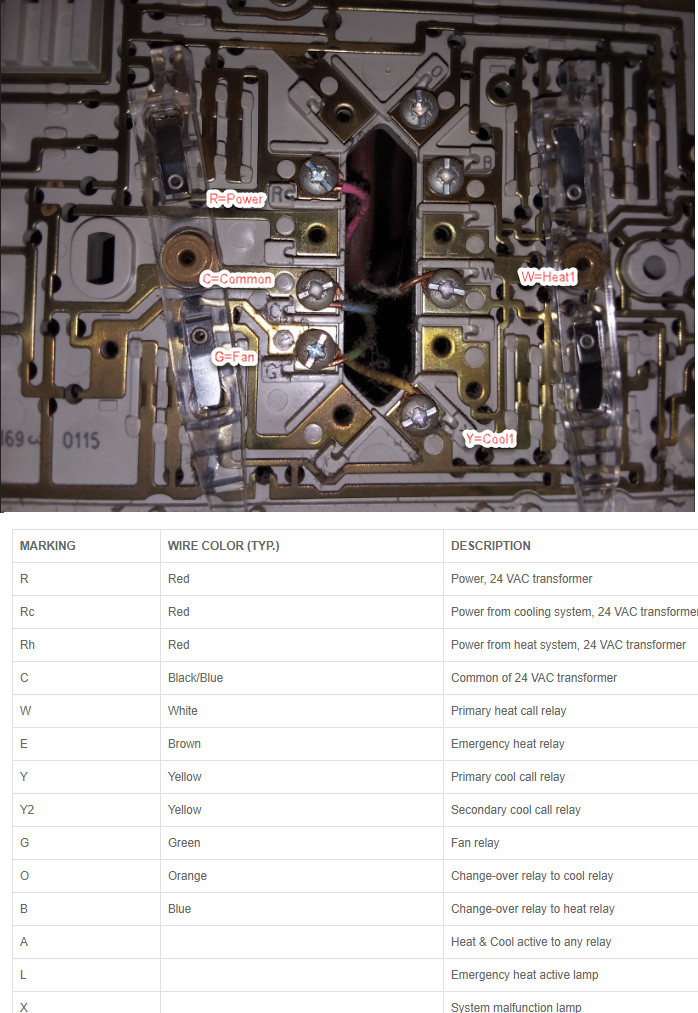
Here is a photo of the backplate which shows the classic RCGWY naming convention for the equipment connections and their typical wire colors. The setup of the Tstat8 follows further down.
Wire naming & color scheme:
R = 24vac power, red wire
C = 24VAC common, black or blue wire
G = Fan, green wire.
Y = Cooling, yellow wire.
W = Heating, white wire.
This application is for a single speed fan with one stage of heat and one stage of cooling. The setup for the Tstat8 is shown below.
To be done: Add a Tstat8 wiring diagram here.
First connect to the thermostat with the T3000 software which you can download from the product pages, the link is repeated here for reference:
https://temcocontrols.com/ftp/software/09T3000Software.zip
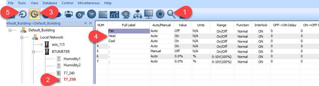
Connect to your PC either through the RS485 port or over the lan if you’re using the new Wifi model. Hit the scan icon at Tab1 and eventually the device will show up in the tree on the left, select the node you will be operating on at Tab2. Then click on the outputs icon at Tab3 & fill in the names of the output relays at Tab4, any relay can perform any function but by convention I put the fan first, then heat followed by cool. The Honeywell T8196 doesnt have any external inputs but feel free to add some extra sensors to your application and configure them at Tab5. The Tstat8 has eight universal inputs which can be used for filter switches, outside temperature sensors and so on.
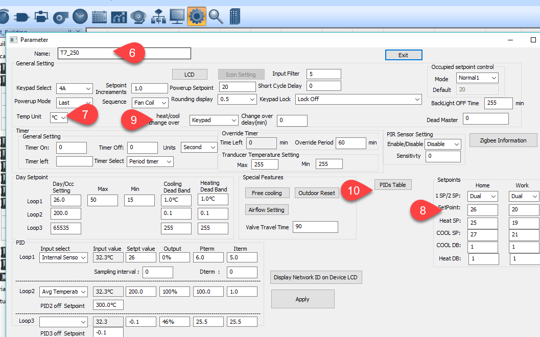
Click on the gear icon up near Tab1 to bring up the advanced setup dialog. Most items are for more specialized applications, the important items are listed here
Tab6: Give the thermostat a name up to 21 characters long here.
Tab7: Set the units to DegC or F
Tab8: Set up your day & night setpoints here, to keep things simple go with the defaults for now.
Tab9: Changeover from heat to cool can be handled automatically or manually at the keypad, select that here.
Tab10: This is the ‘PID table’ where we define the output staging. More on that further down.
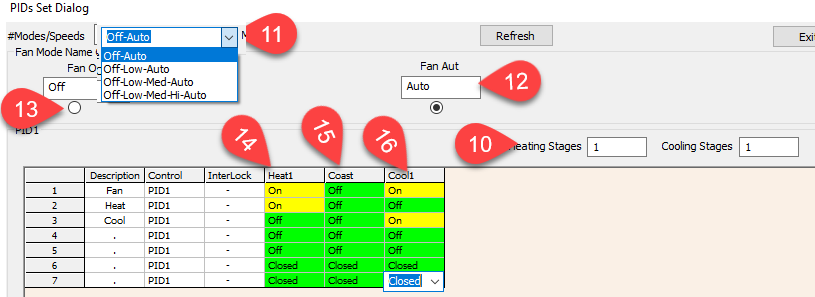
Here is the output table which pops up after selecting the ‘PIDs Table’ button at Tab9 up above.
Tab10: Set the number of heating and cooling stages here, 1 and 1.
Tab11: Set the number of modes here, keeping things simple we use the first one with only two modes. The system will have some default names which may not confusing at first but you can change these names at Tab12 and 13 to suit your application.
Tab12: This is the occupied mode, the default name is Auto and that works fine for this application.
Tab13: This is the unoccupied mode name, the default of OFF also works fine.
Notice the radio button is selected below the ‘Auto’ mode name here at Tab12, there is one table to be filled in for each mode and currently we’re viewing the Auto table. The Auto table is showing in table grid down below. Fill in which outputs will be on in heating stage in the heating column at Tab14, in this case we have the fan and the heat output on, the rest of the outputs are off.
At Tab15 we have the coasting column, all the outputs will be off when the space temperature is satisfied.
At Tab 16 is the cooling colum, the fan and the cooling output will be on in cool mode.
All the rest of the outputs are off for all stages.
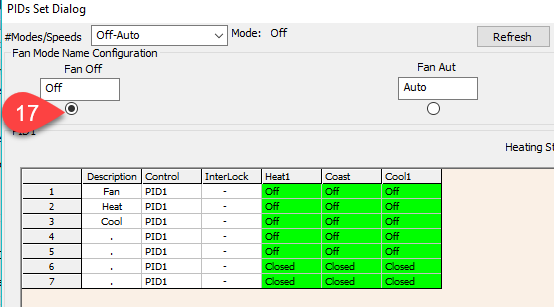
The last step for these output tables is to configure the OFF mode outputs, select the radio button at Tab 17 to bring up another table and set all the outputs to the OFF state for all stages. Alternatively you could copy the table from the above Auto settings and let the stat maintain the night setpoints, but we’ll keep things simple and set everything to OFF at night assuming a commercial application where there’s nobody in the building after hours.
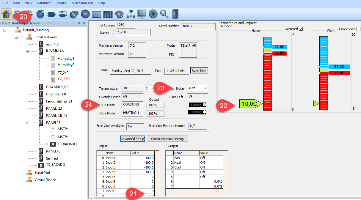
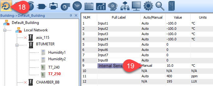
You can test the setup by simulating a high and low temperature in the space by manually forcing the temperature reading. To do that, head to the inputs table at Tab18 and force the item to Manual mode at Tab19. Then type in the simulated values to the right and then watch the stat stage to heat and cool as appropriate.
Click on the home icon at Tab20 to bring up the main ‘User view’ of the thermostat. The simulated temeprature we entered before is shown at Tab21 and also on the sliders to the right at Tab22. You can adjust the day and night setpoints by sliding the blue and red sliders, in this case we have a heating setpoint of 25C and a cooling setpoint of 27C. With the room temperature at 10C this stat should clearly be in heating mode but the mode showing at Tab24 is coasting which could be attributed to some changeover timers, I will have my team investigate and add something to the user interface to make this more obvious.
The config file for this application can be saved using the T3000 software → File → ‘Save as’ which stores all the settings in a text file that can be copied to other thermostats. This config file is included in the general zip file of example configs and is posted here, look for the item called 1Heat1Cool1Fan.txt
https://temcocontrols.com/ftp/software/21TstatExampleConfigs.zip