Setting Up From Beginning

Hi. I just bought T3000 LB. Before this I am using others brand that used Ladder Diagram as the based to the programming. I am not familiar with the others type of programming.
So, here I am starting from zero to build the whole BAS system by using TEMCO. Starting from programming until graphics. I really need help on how to the programming. Is the any template for Air Handling Unit that I can use to study and test? For now I only able to read the temperature into the device.

Thanks .

Thanks for your post here on the forum ShahM, I can help you put together a pogram for you.

-Enter the i/o list into a controller and do a file-> save as, then then send the resulting *.prog file to me by email I will work up the example with you and post it here as another example for others to learn from.

-Here are a few example files on the ftp site: ExampleProgramFiles and there are a few examples in the T3000 help system, hit F1 from anywhere in T3000 to bring up the help system.

Attached is the I/O for the programs.
1)AHU start - DO send the signal to relay
2)Setpoint will base on Temperature value, If Temp > Setpoint , Modulating valve will open 100%. (AO will send 10V)
If Temp < Setpoint ,Modulating valve will open only 30%. (AO will send 3V)
3)Pressure will control the Variable speed drive.(VSD)

Thanks for the fast reply. :smiley:

AHU.prog (64.5 KB)

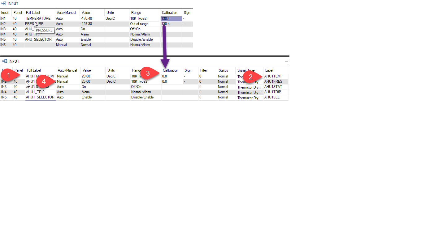
First thing I can suggest is to fill in the name of the I/O with a number so you can copy this program easily to more AHU’s later on. Instead of ‘TEMPERATURE’ we can name that as AHU1 TEMPERATURE for example.

At Tab2 I have also added a short label, these 8 char names are used in the programming while the longer 20 character name at Tab1 is used only in the graphical displays.

I also notice you have a very large calibration factor at Tab3, perhaps you were experimenting with no actual sensor attached. Rather than add the large calibration factor you can put the item into manual at Tab4 and type in a new value. Just remember to put the item back into auto once you start commissioning.


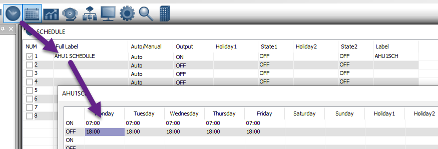
Next I added a schedule and gave it a name.

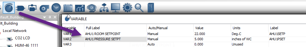
And added a couple of variables, one to hold the room temp setpoint and one for the pressure setting.

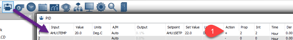
Next create the PID loops, one for room temp and one for pressure control

While doing that I realized we need to set up the custom analog table for the pressure sensor on input 2. I just threw in some numbers for a ‘10inch water column’ sensor operating over 0-10V control signal. You can edit to suit your particular pressure sensor easily. Pay particular attention to the Signal type setting at Tab5, this is where you select 0-10V, 4-20ma, 0-5V or whatever type of sensor signal you have.

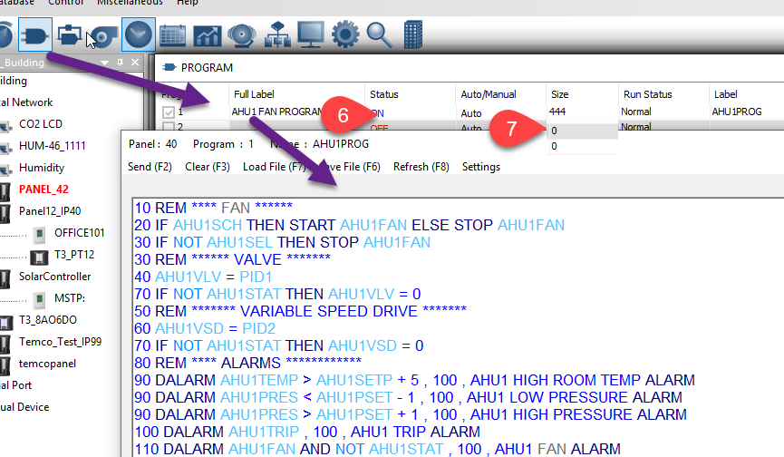
Then I did a very quick program, feel free to tweak and add more logic. The alarm programs will trigger an alarm when the high temp or other condition is met for 100 seconds. The progrm is running as shown at Tab6 and your other two programs further down are OFF. Programs will fight with each other so it will be best for you to delete those other two programs you had in the controller, at Tab7 they show as zeroed out now.

Two things to remember for folks new to this system:

  1. You dont need a goto line at the end of the program to jump back up to the start, that is handled automatically after each run through the logic by the controller. Just let the program flow from the top line to the bottom, keep all lines for each output close together as shown and certainly dont spread logic for a given output to another program.

  2. Lines further down have higher priority than the lines further up, so line 30 for the fan selector switch will override the line 20 with the schedule.

To be done: I notice the line numbers are not auto-refreshing. They’re only used for gotos which I never use myself. Still, I’ll have our developer automatically renumber programs when you hit send.

Here’s the program at this point:
AHU1Rev1.prog (64.5 KB)

To be done: Graphics. Searching this forum for graphics and you’ll see a good example or two. Source for Graphics
image

30 REM ****** VALVE *******
40 AHU1VLV = PID1

Sir, I dont understand how does the valve will be controlled by PID.
Why did the setpoint at PID column is 40-Var1. ?

10 AHU1VLV = PID1

AHU1VLV is the output for the valve, OUT1

PID1 is the first PID in the list of PIDs.

If PID1 is 100, the valve will be at 100%.
If PID1 is 50, the valve will be at 50%
and so on.

40 just happens to be the panel ID, you can change it in the advanced settings area.

Orite.I have tried the PID function. how can I make the minimum output is 30%? Is there any setting?
I have able to make the output follows the value inside PID.

That’s an easy one and you’ll use this a lot:

10 OUT1 = MAX( 30 , PID1 )

1 Like

Thanks Sir,
May I know if I want to use it as slave, where do I have to get the modbus register for the device?
One more things, what is the functions of value number,(for example 10 infront of the 10 OUT1 = MAX( 30 , PID1 )

I have read your post about the modbus register, I can view it from Register View but the register is not tally. For example, 48092 is for variable 1 but when I check variable 1 actually in 48094. Is there anything I need to do to update the value?

10: This is the line number. Its not actually used except for goto statements.

Modbus Register View Ttool: All the inputs, variables and other parameters of the device are available using Modbus calls over Ethernet and/or the RS485 subnetworks. There is no need to specify if this device is a master or a slave. You mention the register table seems to be offset by ‘2’. I will ask our team to check the list. Remember that modbus registers are base0 which makes them one less than if they were base1.

Ok sir. Tq so much :slight_smile:

Hi All, A couple of questions

  1. Once you’ve connected to a T3 controller and have the T3 controller in your system tree. Can you now write the software not connected to the T3 controller and then send the program to the T3 controller at a later date?
  2. How do I know that the T3 controller has taken the program? In other words, how can I see the program is located and running in the T3 controller I sent the program too?

Thanks in advance.

Offline Programming: You can program offline and save the results to a *.prog file and later send that prog file to a controller. The only hitch about offline programming is that you will not see the program running. You can edit and check it for syntax, send it to the offline virtual controller and so on but you will not see any logic acting & changing outputs or variables, etc. You need to send the program file to a controller to see the program doing that.

Sending a program: When you hit the F2 function key at Tab1 to send a program to a controller there is a dialog at Tab2 which pops up to show that the syntax was good and that the program was sent to the controller. This is true for both offline and online programming. When you send the program online to a controller you can see the program scan time at Tab3 which tells you the program is running.

image

Maurice how can I open the offline proramming tab?

To get to the programming grid you can click on the ‘logic’ icon, I added an arrow to the image above.

Hello Maurice yes later I noticed that I need to have a Virtual device to open it, that was my problem

Note that with the offline programming mode you can do all data entry, do programming and save the resulting prog files. The only thing you cannot do in offline mode is see the program actually running, the fans and pumps will not go on and off according to your program for example. To see that you will need an actual device like the Tstat10 to run the logic.

Do you have an example how the logic looks like, because i did not see it yet

You’re right, I need to do an example or two. Will do that shortly.

For today you could have a look in the help system of T3000, hit the F1 function key to bring that up. Or you can navigate in the T3000 menu system to T3000 → help → contents.

From there you can see a simple example for single stage heating.