This system is an example for a fan control system in a warehouse. A fan on the ceiling is modulated to maintain a fixed DeltaT temperature between the ceiling temperature and a room sensor located lower down in the space. As the heat builds up near the ceiling the fan speeds up. When the difference between the ceiling temperature and the space temperature is small the fan slows down and eventually stops. The fans are enabled when the occupied schedule is active and are off at night. A hardwared interlock with the fire alarm system shuts the fans off via a relay. One auxiliary contact on the fire alarm feeds into an input on the controller as well for a software based shutdown and logging of fire alarm events.
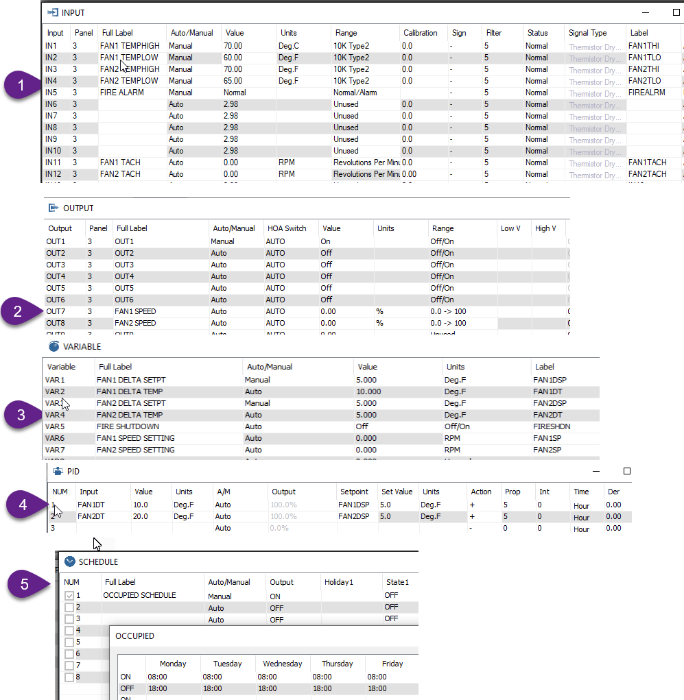
At Tab1 we fill in the inputs. A tachometer input on each fan shows the actual speed and there are two temperature sensors for each zone, one located high up near the ceiling and another lower down at chest height in the space. Note that the tach input is a high speed input, you may need to shuffle the location to another input depending on which controller you are working with.
[Update] I had to move the tachometer inputs to inputs 10 and 11, it must be a high speed input for using the RPM range. We’ve updated the user interface to make sure you cannot select RPM if the hardware doesn’t support high speed counters.
At Tab2 we fill in the outputs, these are the analog outputs on a T3-LB controller. If you are using a different model you will need to move these to a different output position.
At Tab3 are the variables, one to store the delta temperature for each zone and one to store the delta temperature setpoint or target. I have arbitrarily put in a Delta T of 5 DegF, the user can adjust these to suite the space conditions. A lower Delta T setting will cause the fans to run at higher speed for longer periods so you’ll have to trade off between energy savings from lower Delta T versus fan energy consumption.
Tab4 shows the PID controllers, the input to the PID is the delta T variable and the setpoint is your delta T setpoint of course. The Action column is a ‘+’ sign since when the Delta T is above setpoint we want more action from the PID, generally cooling is ‘+’ and heating is ‘-’. I have set the P term to 5 which means we need 5 degrees deviation from the target to elicit 100% response from the system. You can tune this number larger for a lazier acting fan and smaller for a more hyperactive fan. I have left the I and D term at zero for simplicity, feel free to add some Integral term later which will kick the system along during periods of slight offset from setpoint.
Tab5 shows the schedule and is self explanatory.
Here’s the program, in lines 20 and 30 we calculate the difference in temperature between the high and low sensor for each zone and store the result in a variable, FAN1DT
Lines 50 and 60 set the fan speed based on the PIDs for each zone. If the schedule is not active the fans will be off.
Lines 80 and 90 calculate the fan speed in RPM from the analog output signal which is used in the alarms. 0-10V scales to 0-2000 rpm at full speed, for example.
Lines 100 and 110 disable the fans if the fire alarm is active.
Lines 150 and onward generate the alarms, the DALARM statement allows a delay before generating an alarm to reduce false triggers from short events.
10 REM ******CALCULATE DELTA T FOR EACH ZONE *************
20 FAN1DT = FAN1THI - FAN1TLO
30 FAN2DT = FAN2THI - FAN2TLO
40 REM ********* SET THE FAN SPEED USING THE PID FOR EACH ZONE **********
50 IF OCCUPIED THEN FAN1OUT = PID1 ELSE FAN1OUT = 0
60 IF OCCUPIED THEN FAN2OUT = PID2 ELSE FAN2OUT = 0
70 REM *** CALCULATE FAN REQUESTED SPEED FROM % ********
80 FAN1SP = 2000 * FAN1OUT
90 FAN1SP = 2000 * FAN1OUT
100 REM ********* FIRE ALARM SHUTDOWN *********
110 REM THIS IS A SOFTWARE SHUTDOWN,
120 REM THERE’S ALSO A HARDWIRED INTERLOCK
130 IF FIREALRM THEN FAN1OUT = 0
140 IF FIREALRM THEN FAN2OUT = 0
150 REM ******* ALARMS *************
160 DALARM FAN1TACH < FAN1SP - 100 , 100 , FAN1 LOW SPEED ALARM
170 DALARM FAN2TACH < FAN2SP - 100 , 100 , FAN2 LOW SPEED ALARM
180 DALARM FIREALRM , 10 , FIRE ALARM DETECTED
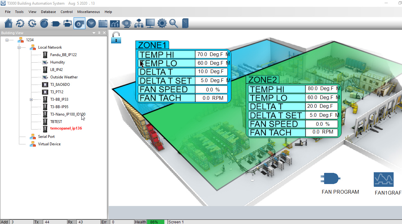
And here’s a screen shot of the system with some graphics. I borrowed the warehouse image from some on line clip art and added the tables using Corel Draw. If you need help with generating graphics send us an email and we’ll be glad to help out.
Here’s the program developed for this application, it was done on a T3-LB so you may have to move the analog outputs around to match your hardware. Also many of the inputs and so on are left in -M manual override mode for debugging purposes, you will switch them to auto once you have the sensors wired in and are ready to see the system in action.
FanControllerRev2.zip (345.2 KB)
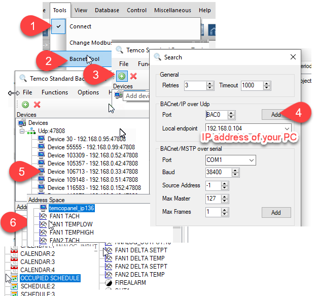
Also may as well note that all the inputs, outputs, variables, schedules and so on mentioned above are available as Bacnet objects and Modbus registers to other systems in the building. This means you can integrate this fan controller into an existing building automation system if there is one already.
You can see the Bacnet objects using the Bacnet tool from withing T3000, or any other 3rd party Bacnet explorer.
Maurice,
This is a good practical example. The P setting (Prop) was a bit of a mystery to me before. Now I understand it and have better control of the VFD in my cooling tower as a result. Thanks!
System is working quite well. Great effort here Maurice.