Damper Analog Output mapping versus flow setting

Are custom AO ranges possible?

Looking for the ability range my 2-10v AO as 90-1200CFM. The AO’s don’t have custom ranges like the AI’s do.

If not, can I set up an AI with my custom range and use a linear equation in Basic to drive the AO?

Or is there a span function to span the 2-10v_9-1200cfm AI to the 2-10v_0-100% AO?

1 Like

Similar to the outdoor temperature reset formula, you have the two points and will need to dig way back to middle school math to generate a general forumula for a line between two points.

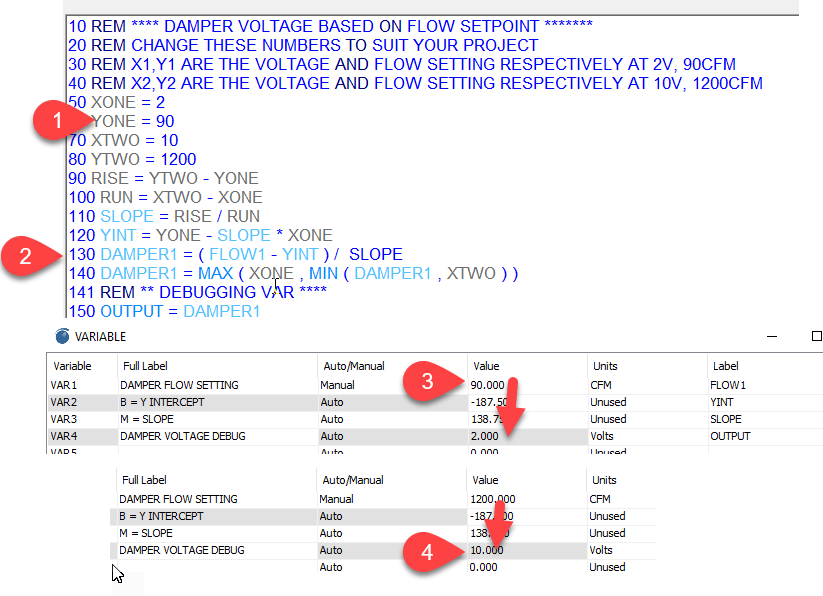
10 REM **** DAMPER VOLTAGE BASED ON FLOW SETPOINT *******
20 REM CHANGE THESE NUMBERS TO SUIT YOUR PROJECT
30 REM X1,Y1 ARE THE VOLTAGE AND FLOW SETTING RESPECTIVELY AT 2V, 90CFM
40 REM X2,Y2 ARE THE VOLTAGE AND FLOW SETTING RESPECTIVELY AT 10V, 1200CFM
50 XONE = 2
60 YONE = 90
70 XTWO = 10
80 YTWO = 1200
90 RISE = YTWO - YONE
100 RUN = XTWO - XONE
110 SLOPE = RISE / RUN
120 YINT = YONE - SLOPE * XONE
130 DAMPER1 = ( FLOW1 - YINT ) / SLOPE
140 DAMPER1 = MAX ( XONE , MIN ( DAMPER1 , XTWO ) )
141 REM ** DEBUGGING VAR ****
150 OUTPUT = DAMPER1

Here’s a screen shot of what you’ll see in T3000. I have saved the prog file at the link below for loading into your own controller there. The grey items in the program are local variables which are help only in memory of the T3 controller. The blue items are global variables which we can see in the vars table.

VAR1 is the flow setpoint in CFM, you can set this to metric or other units by clicking on the range column and selecting from the various built in ranges or make your own.

Notice that VAR1 is in manual mode for now, this lets you set the flow setpoint manually to watch what happens with the damper output voltage math. Setting it to 90CFM sends the damper to 2V at Tab3 and setting it to 1200 sends the damper voltage to 10V.

Line 140 clips the damper voltage to the minimum of 2V and the maximum of 10V.

Line 150 is just for easy debugging and can be deleted once you are done with it, this var lets you temporarily mirror the damper voltage from the outputs table in the vars table while you are testing.

The difference between this example and the outdoor reset example is we’re varying the air flow, the Y parameter and solving for the X parameter, the damper voltage. So the math in line 130 solves for X in this example.

Here’s the prog file, this is done on a T3-BB so you will need to move the DAMPER1 on output13 to a spare analog output on your particular hardware.

FlowSetpoint_DamperVolts.prog (65.6 KB)

1 Like

Maurice, thank you.
I tried modifying the OAT reset you mentioned and it doesn’t seem to be working.

Yes the feature may not have been fully implemented on the Tstat8. Normally we’d work on it more but the focus these days is on the Tstat10. With the '10 you can program it in control basic in a jiffy.

Maurice, if this cannot be programmed as expected, can you recommend a controller for what I’m trying to do?

I’m in search of a very basic BACnet controller with at least one AI and one AO.
The AI needs a 2-10v custom range for a CFM feedback.
The AO needs a 2-10v custom range for a FLOW command.

What I’m trying to do is write a FLOW setpoint via Bacnet MSTP to an analog variable.
The AV range will match the AO’s and will drive the AO directly, no pid.
Is this something that can be done with the T3-OEM I have? I’m new to programming in basic so I may have written the program Incorrectly.

Thanks Again

The Tstat10 is fully programmable so I’d say if you are evaluating the Tstat8 for a new and ‘slightly’ advanced project with outdoor reset then for sure you should consider the Tstat10 for this application. The above sequence will be done in 15 or so lines, search this forum for ‘outdoor reset’ to see an example.

Update: Completed the example program up above for damper voltage versus air flow setting.

Maruice,

Made progress and have a working demo. Modified the OA reset logic as below. The program runs correctly now and works as expected. Got hung up trying to reverse the action of the AO by adjusting the Low Volt, High Volt parameters as it didn’t actually change the output. So I finally reversed X/Y span parameters and it works.
Thank you!

10 REM SPAN AN INPUT TO AN OUTPUT, LINE “40 XONE = CFM MIN” AND “60 XTWO = CFM MAX”
20 REM X1,Y1 ARE THE FLOW_CMD AND FLOW_OUT RESPECTIVELY AT MIN FLOW
30 REM X2,Y2 ARE THE FLOW_CMD AND FLOW_OUT RESPECTIVELY AT MAX FLOW
40 XONE = 1000
50 YONE = 100
60 XTWO = 0
70 YTWO = 0
80 RISE = YTWO - YONE
90 RUN = XTWO - XONE
100 SLOPE = RISE / RUN
110 BINT = YONE - SLOPE * XONE
120 FLOW_OUT = SLOPE * FLOW_CMD + BINT
130 FLOW_OUT = MIN ( YONE , MAX ( FLOW_OUT , YTWO ) )

I just noticed you updated the post above with a program, thank you so much. Yours adds some more adjustability, good job!