How to program a PWM output
the output is at 3V and not at 3 seconds
equipment used
T3-TB output A01
How to program a PWM output
the output is at 3V and not at 3 seconds
equipment used
T3-TB output A01
While checking on this I see we have some work to do to get it functioning properly from the GUI, this will be fixed and pushed out with the next weekly update.
In the mean time you can use the time-on command from control basic.
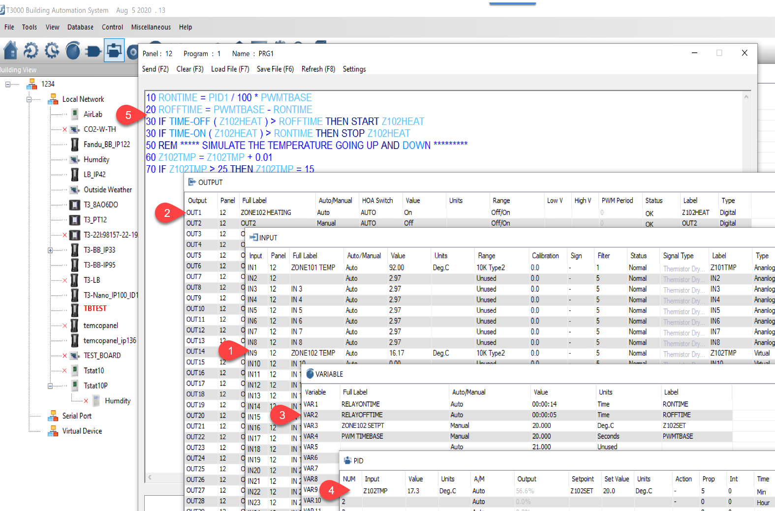
I set this example up on a T3-TB which has input 1 thru 8 making in9 available as a virtual input which we can program with a ramp to test the operation.
Output1 is the heating output, on-off range. We will pulse it on and off in PWM manner but as far as the T3 controller is concerned its a binary output. It could be one of the relay outputs or the analog outputs, both can be configured as binary outputs. The analog output would normally be used and wired to a solid state relay which can handle the pulses over an extended period better than a relay would of course.
Vars 1 and 2 store the time on and time-off of the PWM pulse. Var3 stores the zone setpoint and Var4 is the timebase for the pulse, you could adjust that larger which will reduce the cycling.
The PID loop is configured here, notice the ‘Action’ column is set to ‘-’ which means it will get larger as the temperature falls below setpoint which is what we want for heating. The P term is set to 5 which is fairly large if using a space temperature sensor but would be about right for a supply temperature sensor. 5 Degrees away from setpoint elicits a full 100% response. The I and D terms are left at zero to keep things simple.
And here’s the program. Line 10 and 20 calculate how long the output will be on and off for each given cycle. Lines 30 and 40 do the pulsing of the relay. Lines 50 and onward are just driving the simulated temperature in a ramp for the example.
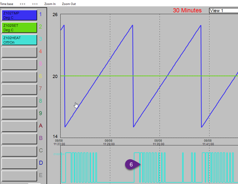
And finally, the results of the test. The simulated temperature sawtooth and setpoint are up top. Down below at Tab6 you see the relay pulsing on and off, its on nearly full time when the temperature falls well below the setpoint with the pulses getting shorter as the temperature gets closer to setpoint. When the temperature is over the setpoint the relay is off as expected.
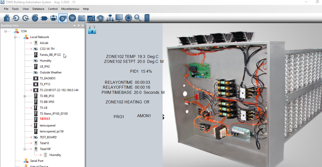
During debugging it helps to put all the IO, vars, programs and trend logs onto a single display. I’ve added an image here to showcase the T3000 graphics capabilities here which some folks may not be familiar with.
Here’s the program used to generate this example:
PWMExample.prog (65.0 KB)