1. Above mentioned packet format is correct? Are we receiving it with a correct time interval of around ~800ms?
The packet format looks correct. I think time interval should be 8000ms. 2. How can we apply a switch input to #1 input? What is the input voltage level for switch On/Off?
For switch on, the input voltage should be higher than 2.6V. 3. How can we retrieve input voltage level (From Byte-1 and Byte-2), Analong input-1(From Byte-4 and Byte-5) and Analog input-2(From Byte-6 and Byte-7) from the data indication reporting packet?
The analog value is 0-4095, as 0-3.3V, Data Packet: 42 02 01 51 70 FE A4 FF
In the packet you showed, 0x42, 0x02 —0x0242 --power suplly
Formula is : Power supply votage = 0x0242*10/52.08 + 90 = 119, it means 11.9v
the byte 0x01, means switch status
the byte 0x51, modbus id
bytes 0x70 0xFE, first analog input value is 0xFE70, get 12 bit, 0xE70, is about 2.9V
bytes 0xA4 0xFF, second analog input value is 0xFFA4, get 12 bit, is 0xFA4, is about 3.3V
Please help us to understand the calculation you have done. Following is specific queries regarding the calculation you have derived.
For First & Second Analog input What is the calculation formula to derive 2.9V/3.3V?
For power supply voltage calculation, help us to understand the significance of coefficient used in a formula “0x0242*10/52.08 + 90”?
In addition to that, we are getting a packet at 800ms interval and you have mentioned 8 seconds(8000ms) so what should be a probable issue here if you can point out.
We are currently using LM35 temperature sensor on Analog Input #1 and #2 and when we decrease/increase room temperature then we are unable to get updated value via ZigBee packet but at the same time, we are able to measure voltage changes on LM35 pins as per temperature changes.
LM35 is providing voltage 10mV per degree Celsius so our input will be in mV range to the ZIM-3I device(i.e 365mv for temperature 36.5 degreesCelsius). So does it sufficient voltage to Analog input #1 and #2 to monitor?
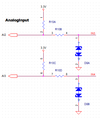
I am afraid LM35 cannot work on ZIM-3I on your hand, because we designed the board for 10k temperature sensor before, so there are pull-up resistors on the board.
If want to use LM32, I think have to remove resistors and connect the lines.
I have now attached 10K NTC thermistor to Analog input #2(Left most input pin of ZIM-3I) and 24v AC power supply to ZIM-3I and now I am receiving ZigBee packet as below, D3 05 01 28 70 FE 0A 01 03
If I convert input supply as per your formula then the value is,
0x5D3*10/52.08 + 90 = 376.2 which means 37.6 voltage and it is not matching with input voltage of 24v.
Question #1: Can you please clarify on this?
If I look into Analog Input #2 data then the voltage I am getting is,
0x10A/0xFFF * 3.3 = 0.2143 and my room temperature is around 29 Degree Celcius.
Question #2: How can we map the measured voltage on Analog input #1 and #2 to the actual temperature?
D3 05 01 28 70 FE 0A 01 03
I saw there are 9 bytes, and if it’s 0x5D3, it must be wrong, the power supply voltage range is 9-36V, could you test 12V or 16V voltage , then check the value.
And if you didn’t connect sensor or something to AI1, 0xAFE looks not right, it should be a value closed to 0xFFF.
Thanks for the pointing out, Actually I have copied packet end byte as well which is 0x03 but it is our device specific so it can be ignored.
I have now attached 10K NTC thermistor to Analog input #2(Left most input pin of ZIM-3I) and 12v DC power supply to ZIM-3I and now I am receiving ZigBee packet as below, 42 02 01 78 70 FE 1C 01
If I look into Analog Input #2 data then the voltage I am getting is,
0x11C/0xFFF * 3.3 = 0.2288 and my room temperature is around 29 Degree Celcius.
Question: How can we map the measured voltage on Analog input #1 and #2 to the actual temperature?
Sorry about that.
I made a mistake about ANI and AN2’s data format. I checked the newest code,in your ZIM-3I’s firmware the data which be send has been converted to temperature(degree C).
so in your sample packet, 0xFE70, 0x11c are temperature, signed , so 0x11c means 28.4℃.
And I am sure the time interval is 800ms this time.
We have one additional question, We have integrated this device in our network by using ZigBee HA profile and now we need to move to ZigBee Pro(ZigBee-3.0) so is this device compatible?
We haven’t work on ZigBee 3.0 before, so I am not if new zigbee pro device is compatible with our ZigBee 2007 product, could you have a try and tell me the result, and we will see what we can do for you.
I have tried to join ZIM-3I on ZigBee pro co-ordinator after enabling custom profile and endpoint support as required by ZIM-3I but your device is unable to communicate(We are not receiving data indication packets as we were receiving with ZigBee 1.2 HA co-ordinator). The ZIM-3I device is successfully sending device announce packet but we are unable to get analog input reading packet at every 800ms on ZigBee pro co-ordinator.
Could you send me an email to coordinate this, I would like to get a sample or two of your devices so we can set up an environment similar to yours and debug along with you. We can return the samples once the integration is complete. My email is on the web site, or you can send to info (at) temcocontrols (dot) com and it will get to me.