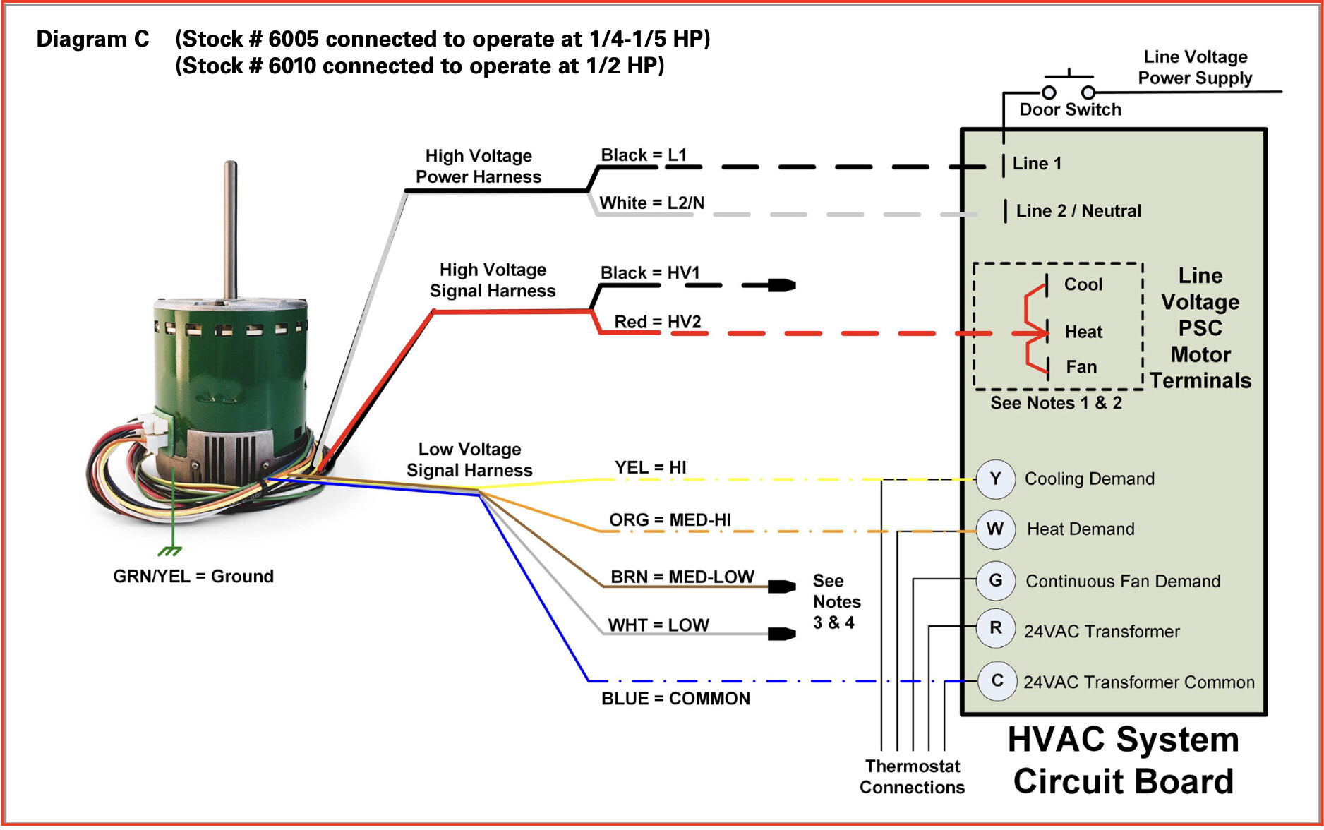
I couldn’t wait any longer for answers to my questions about installing 2 Evergreen IM motors in a FCU, so I installed them but did not connect their LV fan speed signal wires which would result in the motors running at their lowest, most efficient speed. This is sufficient for this cooler season but might be insufficient on the warmest, most humid days, so I wanted to connect 2 of these fan speed signal wires to provide the 3 speeds supported by our thermostat:
Thermostat G1 (L) not connected to a fan speed wire;
and to implement the greatest fan speed range:
Thermostat G2 (M) connected to the ML fan speed wire;
Thermostat G3 (H) connected to the H fan speed wire;
or to implement the lowest fan speeds that we would normally need:
Thermostat G2 (M) connected to the L fan speed wire;
Thermostat G3 (H) connected to the ML fan speed wire;
When these motors are first powered, they perform an automatic rotation sensing procedure by rotating briefly and potentially repeatedly in each direction to determine the correct rotation direction based on the torque required to spin the blower wheels in each direction. With 2 motors sharing the same air plenum, I was concerned that the airflow caused by the blower wheel on one motor might affect the required torque of the other motor potentially resulting in automatic rotation sensing failing or the incorrect rotation detected. Rotation direction could probably have been set manually with a jumper, so this made me wonder whether something other than rotation sensing might be occurring. However, these motors are pre-programmed with no on-site programming possible.
Because of this, I decided to apply power to each motor individually to allow each to sense the correct rotation direction. This seems to have worked correctly.
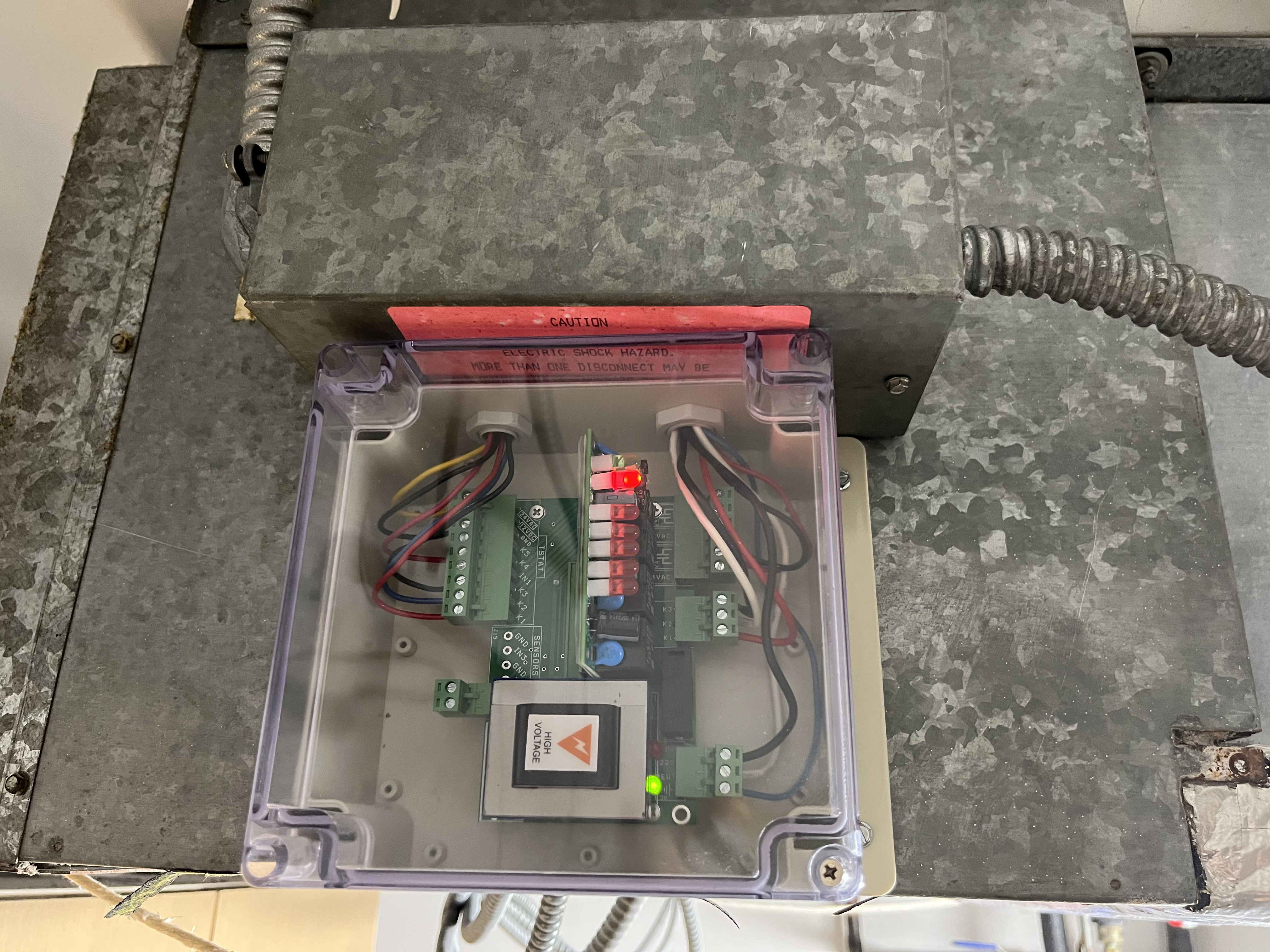
I was concerned about connecting the LV fan speed signal wires because of the high output voltage of the RB-XF-PB-110 FCU control board’s 24 V transformer, ~29 V even with one 24 V fan speed relay and the 24 V cool valve actuator relay being powered. Maybe that load isn’t high enough to reduce the voltage, so I replaced the 120 V cool valve actuator motor with a 24 V version to put an additional 24 V load on the 24 V transformer. As Maurice suggested, this is sufficient to reduce the 24 V transformer’s output voltage to ~25 V.
I then felt confident enough to connect the motors’ LV fan speed signal wires to complete the installation. 3 120 V power wires, 6 thermostat wires, 2 cool valve actuator wires, 18 motor wires, and 11 FCU control board wires must be connected correctly in the wiring junction box. I’m not a fan of conventional wire nuts that could loosen, fall off, expose wiring to short circuits, allow connected wiring to disconnect, etc., so I used 3 2-wire and 17 3-wire Wago 221 Lever-Nuts instead. This resulted in a neater, more secure installation whose wiring connections are less likely to fail. I applied custom labels to each Lever-Nut to document its connection for future reference in addition to using as many color-code wires as possible as shown in the wiring diagram below:
24 V ECM Motors FCU Wiring.pdf (235.0 KB)
I will be testing this installation over the next couple of weeks to determine whether it is reliable enough to leave running for just over 3 months while we’re traveling internationally. Due to the introduction of a FCU control board and motors with integrated electronic controllers that are sensitive to power surges, this modernization will likely be less reliable than the 35-year-old initial system that had never failed. However, early indications are that the Evergreen motors use significantly less electrical energy than the PSC motors that they replaced when running at their lowest low speeds. However, I do not have a way to compare their air flow per watt, so some of the Evergreen motors’ energy savings might be due to their lower fan speed and the replacement of blower wheels whose rusty vanes might have had greater aerodynamic drag.
I’m happy to be finished with this modernization and with the results at this time. The modernized FCU is quieter with no large clacking mechanical relays, less air noise with the new blower wheels, and quieter motors that slowly ramp speed changes including when they’re powered on and off. I’m confident that the cost of running our FCU will be reduced.