The following describes how to do a simple lead/lag program for two circulation pumps. Each week the lead pump is switched to the alternate pump, if one pump fails the other will kick in as backup. The example program and the graphic display are in the example programs are at this link which can be loaded into your own controller for experimenting and learning:
https://temcocontrols.com/ftp/software/16ExampleProgFiles.zip
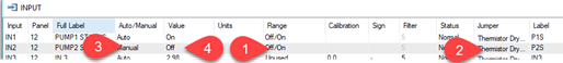
Each pump has a status point which is a binary on-off input wired to the auxiliary contact on the electrical contactor for each pump. First fill in the info for these two inputs, give them a name and set the range by double clicking on the Range cell at tab1 and then select the Off/On range from
the many available ranges. The Jumper column at Tab2 automatically selects
the “Thermistor/Dry contact” mode which is what we want for detecting dry
contact inputs such as a contactor status input. You could also set this up to work with analog current sensors for the pump status, we’ll keep things simple in this example with
a dry contact which shows the contactor state.
Notice the Auto/Manual cell at Tab3, this is how we can simulate and debug
the logic without having the actual hardware installed on site yet, simply
set the mode to Manual and you are now in charge of the state by toggling
the value cell, each hit on the Enter key at Tab4 will flip the input state.
Now do the same for the outputs, give each output a name and set the range
to off-on.

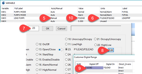
And now set up the variables we’ll need for this example. First we create
two variables to indicate when a pump has failed, one for each pump. The
other item we need is a variable to store which pump is the lead pump.
These variables can also be toggled to manual mode for debugging the
program as shown at Tab5.
Notice the custom Units we have set up at Tab6, this will make it easy to see which pump is currently the lead pump. Set this up by
double clicking on the units cell at Tab6 which pops up the dialog further
down. Enter range 23 at tab7 which corresponds to the first of the custom
binary ranges. Click the edit button at Tab8 and fill in the two custom
names, P1LEAD and P2LEAD in this example.
Put VAR3 into manual mode at Tab10, just we did for the the inputs and outputs up above for debugging, when you are done set it back to auto.
Now we get to the programming part, the IF+ statement in line 30 triggers
once per week on Monday shortly after midnight. OCCUP is a schedule we can build in the schedules grid, it could be any other more complex logic but we keep it simple here with a schedule. The NOT statement flips the LEADMPM variable from zero to one and vice versa each week. Zero corresponds to P1LEAD and one corresponds to P2LEAD.
Lines 40 through 80 are in charge of the pump fail mode variables, if the
output turns on and the status doesn’t show the pump is on as well the
variable will show a pump has failed. If the output goes off or the status
shows on then the fail mode is turned off. If the pump is turned on
manually at the MCC no alarms will be generated. If the output is on and
the pump is turned off manually at the MCC an alarm will be generated but
the alarm will be restored to normal as soon as the MCC is put back into
auto and the pump comes on again.
Line 100 turns the lead pump on according to a schedule in this simple
example, this logic can get more complicated in the real application of
course. The lines at 120 and 130 will turn on the backup pump if either
pump fails. Finally a safety line a 140 is added to stop a condition where two
pumps could be on at the same time, just in case. Lines lower down in the
program take precedence over earlier lines so the safety logic goes last in
your program.
10 REM *** LEAD/LAG PUMP PROGRAM *******
20 REM SWITCH TO A NEW LEAD PUMP ON MONDAY
30 IF+ DOW = 1 THEN LEADPMP = NOT LEADPMP
40 REM ** CHECK FOR A FAILED PUMP ***
50 IF TIME-ON ( P1 ) > 00:00:10 AND NOT P1S THEN START P1FAIL
60 IF TIME-ON ( P2 ) > 00:00:10 AND NOT P2S THEN START P2FAIL
70 IF P1S OR NOT P1 THEN STOP P1FAIL
80 IF P2S OR NOT P2 THEN STOP P2FAIL
90 REM ***** ENABLE PUMPS ACCORDING TO SCHEDULE ************
100 IF OCCUP AND LEADPMP = 0 THEN START P1 ELSE STOP P1
110 IF OCCUP AND LEADPMP = 1 THEN START P2 ELSE STOP P2
120 IF P1FAIL THEN START P2
130 IF P2FAIL THEN START P1
140 IF P1S THEN STOP P2
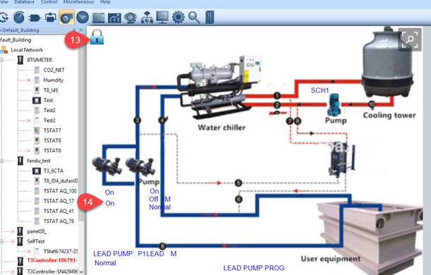
For a final touch we can add all the items to a graphical display and debug
the program by setting various items to manual mode and watching the
behavior.
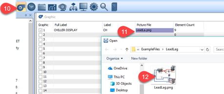
Click on the fan icon at Tab10 to bring up the list of graphics in the
controller, double click on the Picture File cell at Tab11 and navigate to
the image to be used as the backdrop at Tab12. Hit the insert key on any
cell in Row1 to bring up the related graphic display.
Unlock the lock symbol at Tab13 so that you can add elements to the
display, do this by hitting the “INS” insert key anywhere in the graphics
area and typing in a label such as P1, P1S and so on which refer to the
user name of the various items in this system. You can also refer to the
elements as IN1, OUT1 and so on. move the elements on the display using the
mouse, set the display parameters and then lock the display when you’re
done by clicking on the lock icon again.
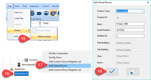
If you do not have hardware on hand to experiment with you can program in
offline mode. The steps here will change slightly in an upcoming version,
you won’t have to select online or offline mode. For now, specify that you
want to work in offline mode at Tab15 and create the virtual device at Tabs
16 through 18.
Now you have created an offline device which you can program without having
hardware on hand. From the T3000 menu select File → Load , navigate to the
example program file and load it into memory. Keep in mind that the actual
programming logic will not run in virtual mode but you can at least edit
the program, save it and later load it to a device. And an item for our programmers to fix
soon, the graphics display in offline mode doesn’t show the real time
elements now, this will be fixed shortly.