I just want to be clear about setting inputs for different input types. There is some mention in documentation of changing jumpers etc to switch between different types - eg switch, Thermistor, Pt1000, 0-10V, 4-20mA. Also, the INPUTS table needs to be set up correctly for different types
For T3-BB (1kPT option), I have the idea that no hardware change (jumpers etc) is required for different input types - all the configuration is done in the INPUTS table. Is this corrrect?
Your understanding is correct — for the T3-BB with the 1k Pt option, no jumper or hardware change is needed when switching between different input types.
The hardware will mux the input signals according to the range setting and can handle all modes: 0-10V, 4-20ma, thermistor and dry contacts.
For 1k Pt sensors there’s some extra hardware required and since its not the most popular hvac type sensor we made this as an option, you need to select 1k Pt compatible during checkout. We can offer the 1k Ot module separately if you ordered a controller without, just send us an email.
With Pt1000 temperature sensors, there is presumably a reference resistor &/or voltage/current source. Please advise the precision/tolerance of the reference(s) and resulting measurement
What is the scaling of the calibration adjustment parameter?
Is it a temperature off-set expressed in 0.1deg increments or something else?
For Pt1000 on T3, there is no internal reference resistor. Accuracy mainly depends on the Pt1000 sensor and wiring.
Calibration works like this: In T3000, you can just enter the offset directly as a number, including decimals. If you change it via Modbus, the value is scaled by 10. So writing 5 means 0.5°C.
I understand the main source of error in temperature measurement is sensor calibration and, for 2-wire sensors, the error associated with lead length. I also understand how to use the calibration parameter to compensate for these errors, although I am uncertain if a single offset adjustment can correct across a wide temperature range.
What I am interested to understand is the fundamental accuracy and resolution of the T3-xB input circuit. I see you use a 12bit ADC which would achieve resolution of approx 0.024%. However the accuracy of any ADC is mainly a function of the reference voltage-source, which typically has a voltage tolerance and temperature-coefficient. Sometimes Vref is integrated within ADC, sometimes a separate Vref is used.
With Pt1000 sensors a current source and reference resistor are often included in the input circuitry to create the input voltage to the ADC - but you say there is no Rref. Perhaps you use a reference current-source into the Pt1000 sensor to generate ADC input voltage. Either way the end result is dependent on a voltage or current source. Perhaps you could explain how the Pt1000 input circuit works so that I can assess the sources of error (which will be common to all channels).
Could you advise what ADC & reference component(s) are used in T3-xB signal conditioning for Pt1000? I can then look up manufacturers datasheets to check basic ADC accuracy.
I have 8 Pt1000 sensors connected to a T3-BB with results spread over a wide range. I plan to calibrate sensors but first want to understand the underlying accuracy of the ADC system so I know what the limits are.
I will connect high-precision (0.01%) resistors to represent 0degC (1k) and 51.5degC (1k2) to review ADC performance, and a specially calibrated 3-wire Pt1000 reference sensor to compare to my normal sensors. I hope to achieve +/-0.5% or +/-0.25degC basic uncertainty (although 0.1degC display resolution).
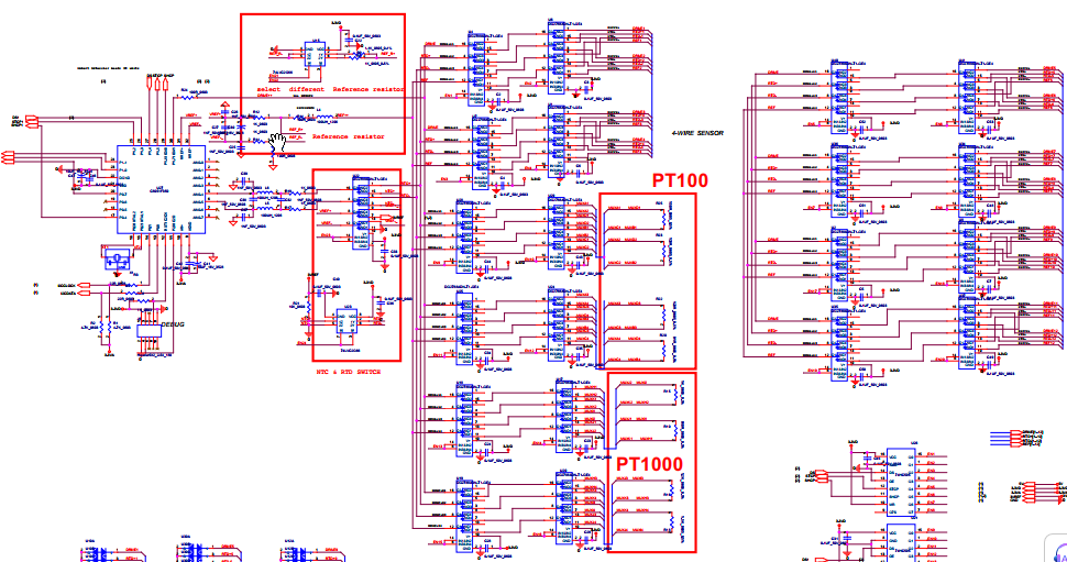
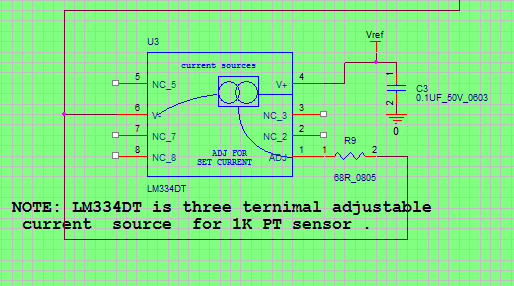
We use a constant current excitation into the Pt1000. The measurement is done with the STM32 internal ADC, using a 3.0 V reference. The excitation current is set with an LM334, with a 68 ohm resistor (1% tolerance). All Pt1000 channels share the same current source and are sampled by the same ADC through channel multiplexing.
The third wire on a 3-wire Pt1000 is only tied in parallel at the terminal and we don’t apply any digital lead resistance compensation, so electrically it behaves like a 2-wire measurement.
Temperature conversion is based on an approximation lookup table.
From an error point of view, anything related to the reference, current source and ADC will be common across all channels. Channel-to-channel spread is usually dominated by sensor tolerance and wiring.
Your plan to test with precision resistors and a calibrated reference sensor makes sense.
Thanks. Based on the details you provided I have revised downwards my expectations about the ultimate measurement tolerance I might achieve - I can/should not expect “lab-quality”. I will be doing fairly well to achieve +/- 0.5degC overall - which is still satisfactory for HVAC applications. (Display resolution of 0.1degC is however rather hopeful.)
The 68R (Rset) resistor means the LM334 sources nominally 1mA current into the Pt1000 sensors. However this is dependent on Rset tolerance (1%) and also the fact the LM334 output varies with its (junction) temperature. (Another use of LM334’s is as a temperature sensor - similar to LM335.) This will cause some discrepancy in combination with the Pt1000 response.
I note that calibration of a LM334 is done by a gain adjustment (although I guess you don’t calibrate the LM334 during manufacture) whereas T3-BB calibration is done by an offset adjustment. I will consider the likely range of temperatures and find the best-fit calibration adjustment.
Far as I know we dont use LM334 in any of our products. Focus your AI searches to 10k tpye 2 and 3. There’s other thermistors but these are the main ones for hvac temp sensors.
Please confer with Lijun who told me an LM334 / 68R resistor are used as a constant current source for Pt1000 sensors in T3-BB-PT1k variant. I am using Pt1000 - not NTC thermistors.
Further update on Pt1000 temperature calibration - refer to previous discussion with Lijun.
My project uses 8 x Pt1000 sensors working in the range 0 to 80degC - I have connected these to Inputs 1 to 8 (2-wire connection).
There are clearly 3 main sources of error:
the Pt1000 sensor itself
the connection wiring. My max length & conductor size may add 0.15degC
the T3-XB input circuitry - current source, ADC etc.
To address The T3-BB input errors, I attached a high-precision (0.01% or 1 part in 10,000) 1k resistor to the T3 Inputs - to represent 0degC. The indicated temperatures across the 8 inputs were in the range -0.8 to -1.5degC. I inserted + calibration figures to achieve 0degC with the resistor connected.
Subsequently I tested with a connected Type A (higher accuracy) 4-wire (connected as parallel-2-wire) Pt1000 in an ice-bath on one input and the indicated temperature was -0.6degC. Ie, the sensor error and T3_BB errors offset each other to some extent.
I am still setting-up an accurate temperature indicator (using my typeA Pt1000) for checking end-to-end calibration of all my inputs. It seems hard to find an affordable indicator, so I plan to build one using a MAX31865 converter module.
(I wonder if this chip might improve the T3_XB - PT1K performance?
The T3-BB series with the 1k Pt option is a simple opamp circuit to boost up the signal to match the 0-3V range of our A/D converters. There’s no 10 turn pots or anything like that to calibrate offset and scale, its the simple offset in the ‘calibration’ field which you are familiar with.
For precision working with 1k Pt’s you should be testing with one of the T3-PT12 units, it has some advanced electronics for self calibrating and 4 wire sensor elements. Its been a while since I looked at it but we were going for instrument grade accuracy as it looks like you are after.
Thank you both for your comments.
I am not trying to achieve lab-quality results - but I would prefer +/- 0.5degC
My testing so far suggests the T3-xB - 1kPt combined with regular 2-wire Pt1000 sensors “out of the box” - achieve +/- 1degC without any calibration.
So I will need calibration adjustments - based on comparison to a more accurate instrument. I suspect I may need both offset and range adjustments. I can use the built-in calibration feature to get offset and - if necessary - will use arithmetic to achieve any scale/range factor.