I am looking to possibly use the T3 units in a greenhouse environment. Can the unit be panel mounted? It kind of looks like the front cover could be removed, mounted on a front panel and the actual electronics mounted inside a sealed box.
For sure, our controllers are used in grow houses, mushroom farms and the like. They will typically be mounted in a metal cabinet panel mount style.
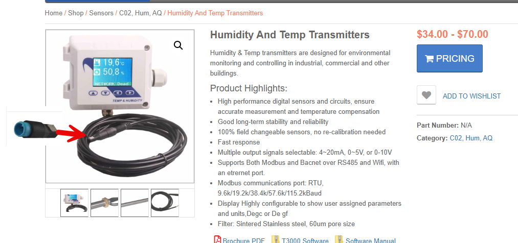
Do check out the new waterproof temp and humidity / temperature sensor moudules with the new waterproof connecto, these are made for harsh environments. If they happen to get sprayed or gunked up you can swap out the sensing element easily.
1 Like
I currently use another programmable thermostat like the Tstat6 but isnt rated for the high humidity environment. I need it to be programmable and have multiple relays/AI/AOs for various motors as well. I was looking at the T3-OEM and surface mount it, where the screen cover is in front of the panel, and the controller is directly behind it. That way it can still be used to change temps but protected from the humidity
We currently dont have a good solution for a panel mount industrial style HMI + controller. Your best bet will be to get a small HMI and integrate over Modbus or Bacnet.
That said, its in the pipeline. We do have some gear in the works. It’ll be a few months though.
@maurice I got a T3-OEM and seems with minimal modification, I can panel mount it nicely for a greenhouse environment, Although I accidently ordered the non-wifi version.
Does the wifi version use the same STM32 chip or an ESP32? Id like to do some firmware modifications so want to make sure I start from the right place.
EDIT: seems the STM32 firmware isnt on github..
Show us your bracket if you dont mind sharing.
The wifi is an add on module, both with wifi and without wifi use the same ST chip.
I dont have any brackets. I havent actually mounted it yet but will send a photo when I do.
I disassembled it, removing the white cover. I’ll make a panel cutout just a little smaller than the cover so I can seal it. That part will sit on the front panel. I’ll remove the LCD’s housing clips on the side. The top and bottom PCBs will sit behind the panel but mounted to the screws.
The only part that will be annoying is that the terminal connector screws are facing forward so I have to disconnect the connector to screw in a wire, but doable. And will probably have to put in a spacer on the buttons depending on the mounting panel thickness.
Its not ideal, but I think its doable. My business partner working in the greenhouses keeps begging me to replace the old tstats because the buttons no longer work due to moisture and comm drop outs from a poor connection on the RS485 from the PCB to the base. When connecting/disconnecting the tstat from the base, the top 3-4 pins dont make a good connection, combined with hot/cold weather cycles, it causes the comms to occasionally drop out.
I’m an engineer so when it comes to the redesign for the esp32, I can provide design feedback/improvements if you would like
I have a cad person on this now, will have something to share in 3-4 days. Its based on the Tstat11 with the touch screen.