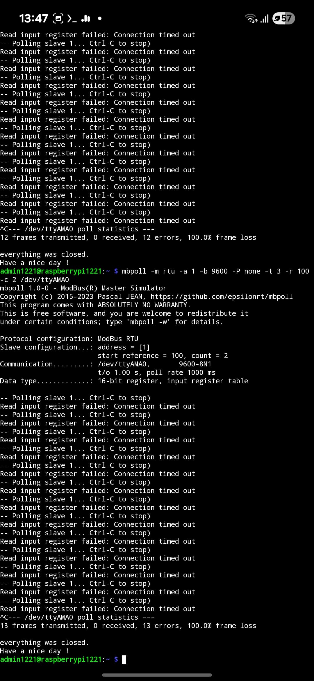
Hello, I am having trouble getting information via RS485 when connected to Raspberry Pi. I updated the T3000 software, got a list of R modbus and wrote the code to read the information, but there is no response from him. I am contacting the same address and baud rate
Tell me, maybe something can be done programmatically on the T3000, maybe there’s something I’m not seeing?
Also for RS485 i’m using Sequent Microsystems Relay 8 ch+RS485 HAT
Code:
#!/usr/bin/env python3
-- coding: utf-8 --
“”"
Simple Modbus RTU reader for the BravoControls single-phase meter.
- Reads CURRENT_VALUE (reg 100) and VOLTAGE_VALUE (reg 101)
- Shows raw values and optionally scaled ones (if needed)
- Includes basic diagnostics for CRC/timeouts and line polarity issues
Requirements:
pip install minimalmodbus pyserial
“”"
import minimalmodbus
import serial
import time
from typing import Optional
==== USER SETTINGS ==========================================================
PORT = “/dev/ttyAMA0” # Your UART/RS485 adapter device
SLAVE_ID = 1 # Modbus address you set in the meter
BAUD = 9600 # 9600 per your device table
PARITY = serial.PARITY_NONE
BYTESIZE = 8
STOPBITS = 1
TIMEOUT_S = 1.0 # Read timeout (seconds)
Holding registers according to your table/screenshot
REG_CURRENT = 100 # CURRENT_VALUE (16-bit unsigned)
REG_VOLTAGE = 101 # VOLTAGE_VALUE (16-bit unsigned)
If the meter returns raw counts that need scaling, set factors here.
If values are already in A and V, leave factors as 1.0.
CURRENT_SCALE = 1.0
VOLTAGE_SCALE = 1.0
============================================================================
def make_instrument() → minimalmodbus.Instrument:
“”“Create and configure a MinimalModbus instrument.”“”
instr = minimalmodbus.Instrument(PORT, SLAVE_ID, mode=minimalmodbus.MODE_RTU)
# Low-level serial configuration (8N1 @ BAUD)
instr.serial.baudrate = BAUD
instr.serial.bytesize = BYTESIZE
instr.serial.parity = PARITY
instr.serial.stopbits = STOPBITS
instr.serial.timeout = TIMEOUT_S
# Optional: settle times on some USB-RS485 dongles
instr.clear_buffers_before_each_transaction = True
instr.close_port_after_each_call = False
return instr
def read_u16(instr: minimalmodbus.Instrument, reg: int, retries: int = 3) → Optional[int]:
“”“Read one 16-bit unsigned holding register with a few retries.”“”
for attempt in range(1, retries + 1):
try:
# function code 3, 0 decimals → returns Python int
val = instr.read_register(reg, 0, functioncode=3, signed=False)
return val
except (IOError, OSError, minimalmodbus.NoResponseError) as e:
# Typical causes: wrong A/B, no termination on ends, bad ID/baud
print(f"[{attempt}/{retries}] Read reg {reg} failed: {e}")
time.sleep(0.2)
return None
def main():
print(“Starting Modbus test…”)
instr = make_instrument()
# Quick line probe: try to read the device ADDRESS register (6) to confirm link.
try:
    dev_addr = instr.read_register(6, 0, functioncode=3, signed=False)
    print(f"Link OK. Meter reports ADDRESS register = {dev_addr}")
    if dev_addr != SLAVE_ID:
        print("⚠️  Mismatch: device ADDRESS != SLAVE_ID you configured here.")
except Exception as e:
    print(f"Link probe failed (reg 6). Reasons could be:\n"
          f"- Wrong A/B polarity on RS-485\n- No/common GND missing\n"
          f"- Wrong ID/baud/parity\n- UART still grabbed by console\n"
          f"- Termination/biasing issue (too heavy loading)\nError: {e}")
    return

# Continuous read loop (Ctrl+C to stop)
while True:
    current_raw = read_u16(instr, REG_CURRENT)
    voltage_raw = read_u16(instr, REG_VOLTAGE)

    if current_raw is None or voltage_raw is None:
        print("No communication with the instrument (no answer)")
    else:
        current_a = current_raw * CURRENT_SCALE
        voltage_v = voltage_raw * VOLTAGE_SCALE
        print(f"Current: {current_a:.2f} A | Voltage: {voltage_v:.2f} V "
              f"(raw: I={current_raw}, U={voltage_raw})")
    time.sleep(1.0)
if name == “main”:
main()
Thanks.