I am having great difficulty in programming a simple sequence - and I dont understand why. My “real-world” situation is more complicated but can be simplified as follows:
There are 2 items of equipment
Item A is started by some logic
Item B starts a set time after Item A starts
item B is stopped by some other logic
Item A stops a set time after Item B stops
So my simple code example is
10 IF IN1 THEN START OUT1
20 IF TIME-ON (OUT1) >0:00:15 THEN START OUT2
30 IF IN2 THEN STOP OUT2
40 IF TIME-OFF (OUT2) > 0:00:15 THEN STOP OUT1
When I test this, neither of the outputs start.
Thinking that because the “off” lines are last, they were counteracting the “on” lines, I tried changing the order to lines 30, 40 , 10, 20 - ie placing the start commands after the stop commands. Then both outputs came on but did not go off.
This is a common-enough requirement, so how do I make it work?
As I mentioned in other threads, it’ll be best to create a local variable to keep track of the timing. You can then see this variable in the vars table, you can place it on displays and add it to the trendlogs.
1. Item A is started by some logic 2. Item B starts a set time after Item A starts 3. item B is stopped by some other logic 4. Item A stops a set time after Item B stops
So here is some pseudo code for your sequence:
10 VAR1 = TIME-ON( A )
20 VAR2 = TIME-OFF( B )
30 IF SOME_LOGIC THEN START A
40 IF VAR1 > 0:01:00 THEN START B
50 IF SOME_LOGIC2 THEN STOP B
60 IF VAR2 > 0:01:00 THEN STOP A
I will use the variable-based timer approach . One problem with using variables for trouble shooting is the variable tables is much slower to refresh than the real logic running in the plc. I already have used numerous variables so I can narrow the problem down to a particular line.
I wonder if I should be using the IF+ function eg to stop turn-on logic interfering with turn-off??
IF+ is good for edge triggered events. It wouldnt help your debugging go any faster but it can clean up a lot of applications like lighting, sequencing of equipment and so on.
Debugging Timers
You can always increase the timers up to 10, 20 , 30 seconds for debugging. Then set them back to the real value when your’e done.
Thanks. I’m usually making my timers shorter for testing.
I tried to monitor unlabelled variables (eg VAR125) in Trends but they did not display. So I gave them labels but still they did not display. Maybe I needed to also define a digital range to have them show as trends? I did notice they moved to the top of the trend list so maybe they were being treated like analogs with a very small value?
Not sure what might be going on but here’s a quick look at the new trend log system. Its a more modern look than we had before. Easier to add features if you need it.
I realise that your pseudo-code is not intended to be complete, but when I tested it, I found a problem.
Basically this code works for just one cycle. After that, VAR2 keeps increasing and line 60 remains true, so line 30 is always over-ruled, so A never starts again. VAR1 is stopped/reset by line 60, but nothing stops/resets VAR2.
I think this explains the results I was getting with my own code.
I am not sure what the solution is. I tried adding a “reset-to-zero” for VAR2 - eg
IF+ NOT A THEN VAR2 = 00:00:00
both after line 60 and also before line 10, but neither worked - VAR2 just kept increasing.
You mention that VAR2 is always increasing, that would be because B is not going off. Since B goes off and is controlled by SOME_LOGIC2, that’s where you need to do your debugging.
-Set up a trend log with all the items in your program including all the vars and IO.
-Build a graphics display with all the same items.
-Manually toggle A and B on and offf, you will be in charge for the time being
Watch the graphics and the trend logs as things go on & off and verify the timers are at least working.
Once you prove that out you can put A into auto and let SOME_LOGIC run and control A. Manually toggle B for now, make sure all seems good with that.
Now prove out the SOME_LOGIC2 which operates on B
While debugging you can coninue with toggling of A, B, VAR1, and VAR2 in manual mode to verify other parts of the program.
Thanks again for your continued support. I am not trying to be obtuse - but probably am anyway!
My testing situation is now more difficult because I am no longer on site and have to access the controller remotely. The controller is busy controlling things, including my small test program. I have to test using inputs and outputs that are already allocated - but I have disabled (by REM) all the other uses. Although this is more clunky it still works.
To make things as simple as possible for testing, I have reduced the “other logic” to a single input controlled manually. I am using the following code:
10 REM - TIMER SEQUENCE TESTS
20 VAR122 = TIME-ON (DO6)
30 VAR123 = TIME-OFF (DO7)
40 IF IN26 THEN START DO6
50 IF VAR122 > 0:00:30 THEN START DO7
60 IF IN27 THEN STOP DO7
70 IF VAR123 > 0:00:30 THEN STOP DO6
VAR122, VAR123 have range 50, “Time”
Starting with all Inputs, Outputs and VARs at zero…this is what I understand happens…
(line 40) IN26 starts DO6 and also starts VAR122 counting
(line 50) when VAR122 exceeds 30sec, DO7 starts (and because DO6 stays on, VAR122 keeps incrementing)
(line 60) IN27 stops DO7, and starts VAR123 incrementing
(line 70) when VAR123 exceeds 30sec, DO6 stops which resets VAR122 to 0.
Critically, VAR123 keeps on incrementing. This means that line 70 (coming lower down the list) always overrules line 40.
Counter VAR123 will keep going until DO7 next comes on - but that requires DO6 to come on, but DO6 is held off by line 70.
As I see it, lines 40 and 60 should only apply briefly so as not to block future restarts - hence my thinking of using IF+ function.
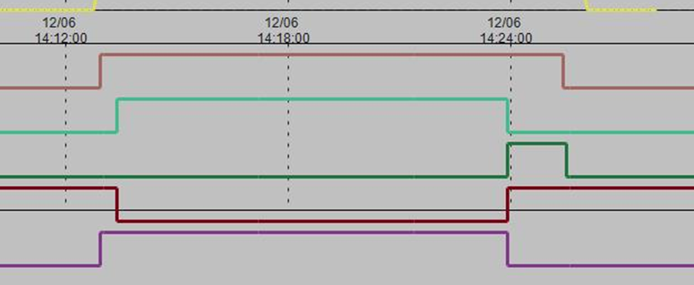
Attached are some screenshots of the evolution to the proper answer.
Of the 5 traces shown, the bottom one is the input which turns-on the top trace. The second (brown) trace turns on a set time later (with some additional logic). When the 2nd trace stops, the top trace stops after a different time interval
The 3rd & 4th traces are additional variables I added to try to fix things.
The first (partial) screenshot is at the point where I had got things working reasonably - except for the “double-bump” of the third trace, which caused a brief loss of the top trace.
By defining the logic for the third trace more precisely (using an IF- function based on 2nd trace) I was able to get what I need. - see second (partial) screenshot.