Maurice
I have used up all my custom tables and need a few more.
Is it possible to create extras ?
Since a little drama with a pressure control wiring I have learnt lots from the experience and as a result have figured how to wire in a few transducers from a former project.
I now have a K Type thermocouple transducer for 1200 degrees C.
Plus a C type transducer to measure 2000 degrees C and delighted they are still working fine.
Just need more custom Tables to accommodate them.
Can you help.
The transducers are 4 to 20 ma units but all different ranges.
The number of custom tables is fixed but there is an easy work around. If you had any other devices in the system, each of these has its own count for the number of custom tables, so adding a device or wiring the sensor to another controller would be one way.
The other thing you could do is a small program in the T3 controller to scale the input from 4-20ma and store the result in a variable.
[Edited] I have done the math for you and made an example program below.
Thanks Maurice
So if I add another expansion module I will get another 5.
I saw some are 10 bit and some 12.
What would be the smallest 12 bit unit or would a LB be the way to go ?
I remember using the old mx+b equation in a CSI EMS system but would have to think hard about using it in a T3000
I only have a T3-PT12 so can’t use that.
We will have to test out the expansion module idea, but at first glance adding expansion modules would indeed get you more custom tables.
A typical 4-20ma transducer signal can normally be represented by a straight line using the simple straight line formula:
y = mx + b
Where,
y = Output from the transducer, the pressure, flow, or other physical reading
x = ma current from the transducer
m = Slope
b = y-intercept point (i.e. the zero reading from the transducer range)
We can write general formulas for m and b and use these to calculate the temperature, flow or other physical reading from the transducer for any given ma signal reading.
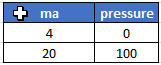
Here is a typical example of a pressure sensor, the output is 4ma at zero pressure and 20ma at the high end of the scale, 100psi for example.
And here is a chart of the pressure versus ma reading from the transducer.
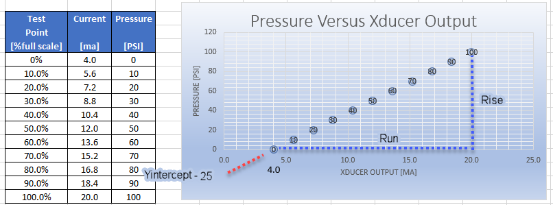
The slope m is rise over the run and since we’re working with a 4-20ma transducer the run is easy to work out, the maximum current minus the minimum current works out to 20ma - 4 ma = 16 ma. The rise is the physical value at the maximum and minimum range of the transducer. In our example this is 100 psi - 0psi = 100psi. So m = 100 / 16 = 6.25. This could be hardcoded in the program or a more general solution can be done as follows:
m = rise / run
m = (MaxValue - MinValue) / (Max_ma - Min_Ma)
And b can be expressed in general terms as follows:
y = mx + b
rearranging:
b = y - mx
Replace the slope m with the general formula from above:
b = y - [ (MaxValue - MinValue) / (Max_Ma - Min_Ma ) * x ]
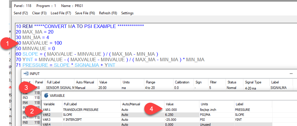
And here’s the results of a program doing as described above. In a real world application you wouldn’t need to create the separate variables for the slope (Var2) and intercept (Var3), they were useful during debugging of the program and are left here for clarity. Tab1 shows the program, grey items are local variables that exist only in memory while this particular program is running. The blue items are either variables or inputs.
Tab2 shows the variables, the one we want is VAR1 which holds the pressure as calculated from the input signal in ma at Tab3. I have the input in manual mode for testing, right now it shows 20ma on the input and Tab4 shows the results of the program which is 100 psi. All you need to adjust in this program is the engineering units and the maxvalue at line 40 to match your actual transducer.
Here’s the spreadsheet used to develop the program: 4-20maTranducerMath.xlsx (11.1 KB)
And here’s the program developed for this example: 4-20maProgram .prog (64.5 KB)
1 Like
So far so good but how to insert this and then to make it useful as a variable a graphics screen would need to be created to display results nicely.
This is all coming back to me but I remember also using a conversion co-efficient which for a 12 bit analogue to digital converter was range of sensor / 2048
So we used had a Custom table where we entered m x and b and the conversion co-efficient and the answer appeared. I guess it’s still a custom table though.
Edit – this was written before i saw Maurices complete reply.
Maurice
Many thanks - this works beautifully an your explanation was most clear.
Tested a number of transducers quickly and found my JUMO -1 bar to 9 bar faulty.
My -1 bar to 1.5 bar vacuum unit is working along with 0 to 10 bar units
Just tried my 0 to 2000 C and 0 to 1200 C transducers and working also.
This calc technique has freed up Custom tables for use nicely.
Again thankyou .
Now you have me curious about the application. What all are you connecting up to here GD?
![]()
So mainly monitoring and logging rather than control - hence a range of tables required.
I was ex Refrigeration so used a lot of transducers in workshop testing.
Worked at the atomic test site Maralinga clean up melting to large contaminated pits to glass and scored C type 2000 degrees transducers and thermocouples there which I now use for my wife’s pottery kilns 1300 degrees.
Also distiller so dream of getting a unit up and running to control a still rather than just monitoring
That looks a bit hard programming wise but am thinking about it.
Programming: Its easy, mostly it’s a lot of ‘if this, then that’.
I can help out with the programming as well. Cheers and thanks for posting.